


INSTALLING THE AT10.1
18
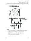
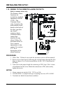
1.10. WIRING TO THE REMOTE ALARM CONTACTS
Built-in common alarm relay
The Primary Alarm
functions are
included as standard
equipment with the
AT10.1. The
Common Alarm
relay, located on the
main control circuit
board on the back of
the door, provides
one form C
summary alarm
(common alarm)
contact that
transfers for any
alarm. Follow the
procedure below to
wire a remote
annunciator to this
contact. See section
2.2.7 for a
description of the
alarm functions.
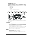
PROCEDURE
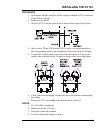
1. Allow 30in / 762mm of wire inside the enclosure (excess will be trimmed).
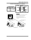
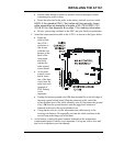
2. Route wires to front door by following the existing harness through the door
hinge as shown. Use (2) wire ties and allow a 4-6in / 102-153mm loop for
the hinge.
3. Trim wires to the proper length for connecting to TB3. Strip .25in / 6.4mm
of insulation from the wires. Make the connections at TB3, and securely
tighten the screws.
NOTES:
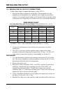
1. Alarm contacts are rated at 0.5A / 125 Vac or Vdc.
2. Terminal block is a compression type, accepting wire sizes #22-14 AWG.
3. Terminals are labeled in non-alarm condition.