


INSTALLING THE AT10.1
16
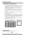
1.9. WIRING THE AT10.1 FOR REMOTE SENSING
You can wire the AT10.1 to regulate the output voltage at the battery
terminals, instead of at the charger output terminals. Remote sensing does
the following:
1. Compensates for voltage drop in the dc wiring between the AT10.1 and the
battery.
2. Directly monitors the battery or dc bus voltage. The front panel meter
displays the actual voltage on the dc bus.
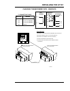
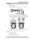
You wire the AT10.1 for remote sensing by installing a two-wire cable
from the AT10.1 remote sense terminals to the battery terminals. The
AT10.1 control circuitry then measures the dc voltage at the battery
terminals, and controls the output of the charger to maintain the battery
voltage at the desired float or equalize voltage.
NOTE: If the remote sense wiring fails, the AT10.1 detects the fault,
and displays E 06 on the front panel meter. See section 3.2 for details.
CAUTION: The AT10.1 cannot protect against short circuits in the
remote sense wiring. You should install a 1.0A fuse at the battery or dc
bus end of the remote sense cable.
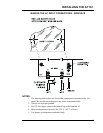
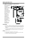
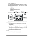
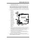
To wire the AT10.1 for remote sensing, follow the procedure and diagram
on the next page.
If you ever need to disable remote sense, follow the steps below:
• De-energize and lock out all ac and dc voltages to the AT10.1. Check
with a voltmeter.
• Disconnect the remote sense wires from the battery or dc bus terminals
first.
CAUTION: You must do the steps above first.
• Remove the remote sense leads from the remote sense (+) and (-)
terminals on the I/O panel. Insulate each lead separately. Coil up the
wires and leave them in the bottom of the charger, in case you want to
wire for remote sense again in the future.
• Reconnect wire # 74 to the dc output (+) terminal.
• Reconnect wire # 72 to the dc output (-) terminal.
• Restart the AT10.1 according to the instructions in section 2.1.