


SERVICING THE AT10.1
61
Replacing the main transformer (T1)
Deenergize and lock out all ac and dc voltage sources to the AT10.1.
Check with a voltmeter before proceeding. This includes remote sense
wires if they were installed. Remove the enclosure shroud and the safety
shield. Disconnect the harness wires # 28 and # 29 from the upper row of
transformer terminals. Disconnect wires # 11 and # 12 from the top of the
rectifier heat sink. Disconnect harness wires # 3 and # 4 from the lower
row of terminals; leave both jumpers in place on the lower row.
Remove the four screws or nuts that secure the transformer to the rear
panel. Support the transformer by the top of the core and lift it up to get
the bottom bracket off the rear panel. Remove the transformer from the
charger.
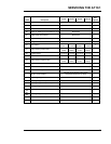
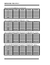
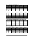
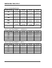
Check the jumpers on the bottom row of terminals of the replacement
transformer. Make sure they are connected to the same terminals as the
jumpers on the transformer you just removed from the charger. For details
see section 1.6, Changing the Transformer Taps.
Hold the replacement transformer with the terminals labeled H1 through
H5 at the bottom, facing you. Place the transformer against the rear panel,
and slide the bottom of the transformer bracket into the slots on the rear
panel. Install the four screws or nuts onto the mounting bracket of the
transformer. Rewire the transformer, following the steps above in reverse.
Refer to section 1.6, and verify that the transformer is properly connected
for your input voltage.
Replacing the ac surge suppressors (VR2, VR4 or VR5)
Turn off all power to the charger. Disconnect the battery from the output
terminals. Remove the safety shield.
For VR2, remove the hardware from the input terminal L1, and remove
the lead of the ac surge suppressor. Install one lead of the replacement
surge suppressor onto the L1 terminal. Replace the other wires and the
hardware. Repeat procedure for the L2 terminal. Tighten all hardware.
For VR4, remove the hardware from the input terminal L1, and remove
the lead of the ac surge suppressor. Install one lead of the replacement
surge suppressor onto the L1 terminal. Replace the other wires and the
hardware. Repeat procedure for the left ground stud. Tighten all hardware.
For VR5, repeat procedure for the ac surge suppressor connected to the L2
terminal and the right ground terminal. Tighten all hardware.
NOTE: The surge suppressors are not polarized.