


OPERATING THE AT10.1
41
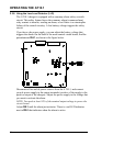
2.4.4. Check temperature compensation probe (optional)
If you are using the optional temperature compensation probe, be sure that
the probe is securely installed. Be sure the connectors and the wiring from
the probe to the AT10.1 charger are in good condition.
If there is a failure of the temperature compensation probe, or the wiring,
the AT10.1 charger displays the error code E 08.
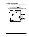
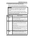
2.4.5. Measuring the output ripple voltage (filtered models only)
If your AT10.1 charger is a filtered model, at least once a year measure
the ac ripple voltage at the battery terminals. Use an rms responding ac
voltmeter.
1
The ripple voltage should be no higher than shown in the
specifications in Appendix A on page 70, if the battery ampere-hour
capacity is at least 4 times the output current rating of the charger.
If you suspect that the output ripple voltage is too high, see "Output ripple
voltage too high" of the Troubleshooting Chart in section 3.4, page 53.
2.4.6. Viewing the voltage and alarm settings
You can review the parameter settings in the AT10.1 charger by pressing
the EDIT/ENTER key on the front panel. Each time you press the key, a
different parameter displays, in the following order:
• Float voltage
• Equalize voltage
• Equalize time (in hours)
• High dc voltage alarm setting
• Low dc voltage alarm setting
• Current limit, in Amperes
1
Don't use a dc voltmeter. The ripple voltage on a battery is a very small ac voltage.