


INSTALLING THE AT10.1
19
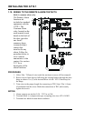
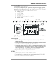
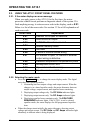
Auxiliary Relay Board (optional)
The Auxiliary Alarm Relay PC Board (A5), mounted inside the separate
top enclosure (penthouse), provides two form C contacts (TB4-1 through
TB4-36) for each of the following individual alarms:
• High DC Voltage
• Low DC Voltage
• DC Output Failure
• AC Failure
• Ground Fault Detection (positive or negative)
• Summary Alarm
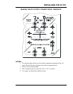
HVDC HVDC LVDC LVDC
DC OUT
FAILURE
DC OUT
FAILURE AC FAIL AC FAIL
GROUND
DETECT
GROUND
DETECT SUMMARY SUMMARY
C, NC, NO C, NC, NO C, NC, NO C, NC, NO C, NC, NO C, NC, NO C, NC, NO C, NC, NO C, NC, NO C, NC, NO C, NC, NO C, NC, NO
1 2 3 4 5 6 7 8 9 10 11 12 13 14 15 16 17 18 19 20 21 22 23 24 25 26 27 28 29 30 31 32 33 34 35 36
Follow the procedure below to wire annunciators to one or more of these
alarm contacts.
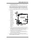
PROCEDURE
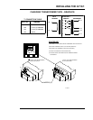
1. Remove the top panel from the penthouse enclosure (on top of the main
charger enclosure).
2. Route your remote annunciator wiring into the penthouse enclosure through
one of the unused knockouts in the side of the enclosure.
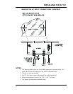
3. Connect the wiring (use #22-14 AWG.) to the appropriate terminals of TB4
on the back wall of the penthouse enclosure (as shown in the drawing at the
right). Strip each wire .25in / 6.4mm, and securely tighten the terminal
screws. The terminals are labeled in the non-alarm condition.
4. Replace the top panel on the penthouse enclosure.
NOTES:
1. Alarm contacts are rated at 0.5A / 125 Vac or Vdc.
2. Terminal block is a compression type, accepting wire sizes #22-14 AWG.
3. Terminals are labeled in non-alarm condition.