


SERVICING THE AT10.1
62
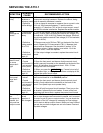
Replacing the dc surge suppressor (VR1)
Turn off all power to the charger. Disconnect the battery from the output
terminals. Remove the safety shield.
Remove the hardware from the output terminal TB1(+), and remove the
lead of the dc surge suppressor. Install one lead of the replacement surge
suppressor. Replace the other wires and the hardware. Repeat for the
output terminal TB1(-). Tighten all hardware.
NOTE: The surge suppressor is not polarized.
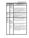
Replacing the dc surge suppressor networks (VR6/C4, VR7/C5)
Replace these networks as assemblies; do not replace individual parts.
Turn off all power to the charger. Disconnect the battery from the output
terminals. Remove the safety shield.
To replace the network VR6/C4, remove the hardware from the output
terminal TB1(-), and remove the lead of the network. Cut the plastic wire
ties holding the assembly tight against the I/O panel. Install one lead of
the replacement network. Replace the other wires and the hardware.
Repeat for the other lead of the network on the ground terminal. For the
VR7/C5 network, use the above procedure, but start with the lead on
TB1(+). Tighten all hardware. Replace cut wire ties if possible.
NOTE: The surge suppressor networks are not polarized.
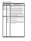
Replacing the power (ballast) resistor (R3)
Turn off all power to the charger. Disconnect the battery from the output
terminals. Remove the safety shield.
Locate the power resistor R3. On 130 Vdc chargers, it is mounted on the
bracket behind the I/O panel. On all other chargers, it is installed just to
the right of the I/O panel. Disconnect the lead of R3 wired to TB1(+), and
replace it with the corresponding lead of the replacement power resistor.
Remove the other lead of R3 from terminal E17 on the I/O panel and
replace it with the remaining lead of the replacement power resistor.
Tighten all hardware.
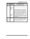
In 12 Vdc through 48 Vdc chargers, align the new R3 next to the I/O
panel so that the leads are properly spaced. In 130 Vdc chargers, remove
the two screws that mount the old resistor, and put the new resistor in its
place. Tighten all hardware.