


TABLE OF CONTENTS
iii
2.3 Setting the AT10.1 parameters
2.3.1 Understanding parameter settings.................................................................30
2.3.2 Setting the Float and Equalize voltages.........................................................31
2.3.3 Setting the Equalize timer ..............................................................................32
2.3.4 Setting the Alarms..........................................................................................32
Setting the high and low dc voltage alarms ...................................................33
Adjusting ground detection sensitivity............................................................34
Disabling the ground detection alarm ............................................................35
2.3.5 Setting the current limit value.........................................................................35
2.3.6 Enabling the high dc voltage shutdown feature.............................................36
2.3.7 Adjusting the Voltmeter accuracy ..................................................................37
2.3.8 Using the Low Level Detector (LLD)..............................................................38
2.3.9 Using the front panel security feature ............................................................39
2.4 Performing routine maintenance ..........................................................................40
Sample preventive maintenance procedure ..................................................42
3 Servicing the AT10.1 Battery Charger
3.1 A step-by-step troubleshooting procedure ...........................................................44
3.2 Interpreting front panel error messages ...............................................................45
3.3 Using the troubleshooting chart............................................................................48
3.4 Troubleshooting chart begins on ..........................................................................49
3.5 Replacing defective components..........................................................................58
3.6 Ordering replacement parts..................................................................................64
Replacement parts tables (begin on)....................................................................64
APPENDIX A: AT10.1 Performance Specifications................................................................70
APPENDIX B: Field Installable Accessories...........................................................................71
APPENDIX C: Standard Drawings
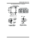
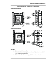
Standard NEMA-1 Enclosure Outline (Style-586)..........................................................72
Standard NEMA-1 Enclosure Outline (Style-594)..........................................................73
Optional Enclosure Outline Drawings (with penthouse and/or drip shield)....................74
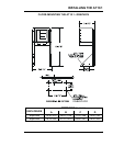
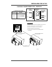
Internal Component Layout Detail w/Common Options.................................................76
Instrument Panel Detail w/Optional Auxiliary Relay PC Board ......................................78
Schematic - AT10.1 Group I Battery Charger - Standard w/o Options ..........................80
Schematic - AT10.1 Group I Battery Charger - with Common Options .........................82
Connection Diagram - AT10.1 Group I Battery Charger - Standard w/o Options..........84
Connection Diagram - AT10.1 Group I Battery Charger - with Common Options .........86
APPENDIX D: Recommended Float / Equalize Voltages.......................................................88
APPENDIX E: DNP3 Level 2 / Modbus Communications Module.........................................89
APPENDIX F: UL Data...............................................................................................................89
CUSTOMER NOTES (manual specifications).............................................................................90