


INSTALLING THE AT10.1
21
• Run the cable though a conduit if possible, but not through a conduit
containing any power wiring.
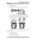
• Route the other end to the probe at the battery and coil up excess cable.
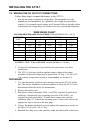
NOTE: If the standard (25ft / 7.6m) cable isn't long enough, longer
cable assemblies are available in lengths of 50, 100 & 200ft / 15.2,
30.5 & 61.0m. See Appendix B on page 71 for ordering information.
• Be sure your wiring conforms to the NEC and your facility requirements.
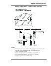
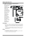
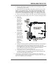
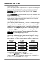
5. Attach the interconnection cable to the AT10.1 as shown in the figure below:
• Route the
cable within
the AT10.1
enclosure so
that it runs
with the wire
harness to the
back of the
front panel,
and easily
reaches the
main control
circuit board.
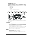
• At the main
control circuit
board, insert
one of the bare
wires from the
cable into each
terminal of
TB8. Polarity
is not
important.
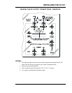
• Unplug the harness ground wire # 30 from terminal J6 on the left edge of
the main control circuit board. Plug the connector at the end of the
nylon-shielded wire of the cable assembly onto J6. Reconnect the ground
wire # 30 from the system harness onto the piggy-back connector
featured at the end of the nylon-shielded wire.
• Using plastic wire ties, tie the interconnection cable loosely to the
existing wire harness. Be especially sure that the cable conforms to the
service loop at the hinge end of the door.
6. At the battery, connect the quick-connect terminals to the temperature
compensation probe. Polarity is not important. Coil up any excess wire and
tape or tie it together to prevent damage.