


INSTALLING THE AT10.1
17
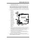
PROCEDURE
1. De-energize and lock out all ac and dc voltages within the AT10.1 enclosure.
Check with a voltmeter.
2. Remove safety shield.
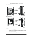
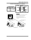
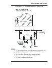
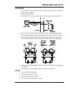
3. Wire the AT10.1 remote sense to the dc bus as shown in the figure below.
4. Move wires # 72 and # 74 from the TB1 (-) and (+) dc output terminals to
the corresponding remote sense terminals as shown in the lower left figure.
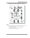
5. Connect the external remote sense leads from the battery or dc bus to the
remote sense terminals on the I/O panel as shown in the lower right figure.
6. Check your work thoroughly. Replace the safety shield before reeneregizing
the charger.
7. Restart the AT10.1 according to the instructions in section 2.1.
NOTES:
1. Use #16 AWG. twisted pair.
2. Maximum current is 150 mA.
3. Run leads in their own conduit.
4. Fuse the wiring at the battery or dc bus.