


OPERATING THE AT10.1
34
Adjusting Ground Detection Sensitivity
You can adjust the sensitivity of
the ground detection alarm circuit.
You must have a test resistor
whose value is the sensitivity you
want. You can adjust the
sensitivity from 5 to 50 kΩ.
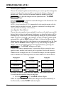
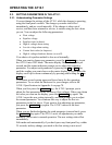
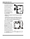
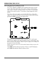
The potentiometer for adjusting
ground detection circuit
sensitivity is located on the main
control circuit board. It is the
lower of the two potentiometers
labeled RA3 SENS, as shown in
the figure at the right.
NOTE: Do not try to adjust the upper potentiometer labeled RA2
BALANCE. This adjustment is made at the factory for proper
circuit operation.
CAUTION: Before connecting or disconnecting a test resistor,
de-energize and lock out all ac and dc voltage sources to the
AT10.1. Check with a voltmeter before proceeding. Restart the
AT10.1 only when necessary to make the sensitivity adjustment.
If your battery is grounded, do not attempt this procedure.
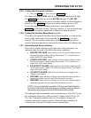
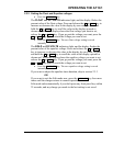
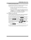
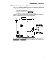
Remove the safety cover. Connect
the test resistor between TB1(+)
and chassis ground, as shown to
the right. Adjust RA3
counterclockwise until the front
panel indicator goes out, then
adjust slowly clockwise until the
POS GND indicator just lights.
Make this adjustment slowly; the
indicator is updated once in every
four seconds. De-energize and
lock out power to the AT10.1,
then remove the test resistor and
verify that the indicator goes out.
Now connect the test resistor between TB1(-) and chassis ground. Verify
that the NEG GND indicator lights. If not, adjust RA3 clockwise until it
does. Remove the test resistor.