


OPERATING THE AT10.1
25
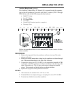
• If you have an optional temperature compensation probe installed, the
front panel displays LEAD during startup, indicating that the
temperature compensation is set up for lead-acid batteries. While this is
being displayed, you can press any front panel key to change the display
to read NICD, to change the temperature compensation setup for nickel
cadmium batteries. The choice you make is saved internally, and will be
used again by the AT10.1 then next time it starts.
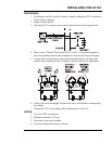
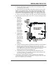
• Turn on the front panel ac circuit breaker. The digital meter displays the
output voltage and current. See Using the Digital Meter on page 24. You
should hear a soft hum from the AT10.1 as the output current increases.
NOTE: If you turn on the ac breaker before the dc breaker,
and you have a filtered model of the AT10.1, there is a
possibility that the dc breaker will trip when you try to turn it
on. This is caused by the filter capacitors discharging into the
battery. To get around this problem, turn off the ac breaker.
Restart the AT10.1 by turning on the dc breaker first.
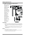
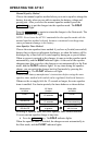
• The green FLOAT indicator lights. Press the CHRG MODE key on the
front panel. The FLOAT indicator goes off, and the yellow EQLZ
indicator lights. Press the CHRG MODE key again to return the charger to
the float mode.
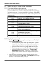
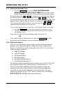
The table below shows the normal factory settings for float and equalize
voltages, equalize time, current limit setting, and alarm settings. If your
purchase order specified other float or equalize voltage settings, a tag
attached to the front panel of the AT10.1 lists the actual voltage settings.
FACTORY SETTINGS FOR ALL PARAMETERS
Nominal Vdc
Parameter
12 24 48 130
Float Voltage
13 26 52 131
Equalize Voltage
14 28 56 139
HVDC Alarm
14.4 28.8 57.6 144
LVDC Alarm
12 24 48 120
Equalize Time
24 Hours
Equalize Method
Manual Timer
Current Limit
110% of nominal output current
HVDC Shutdown
Disabled