


INSTALLING THE AT10.1
8
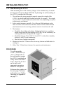
1.5.3. Rack-Mounting the AT10.1
The AT10.1 can be installed in most relay racks with standard EIA hole
spacing (see the table below for the allowable combinations). The rack
mounting kit (part number EI0193-00), includes mounting brackets and
the necessary hardware to install one AT10.1 battery charger. The kit
includes an instruction sheet (JA0091) showing installation details. For kit
availability see ordering information in Appendix B on page 71.
When rack mounting the AT10.1, you must consider the following:
1. The rack must be strong enough to properly support the weight of the
AT10.1. See the Weight Table located in section 1.4 on page 3.
2. Placement of conduit entrances (be sure the knockouts on the sides or
bottom of the charger are accessible after the charger is rack-mounted).
3. The location:
• Should be free of drips and splatter. If dripping liquids are a problem,
install a drip shield kit (part number EI0191-00). For kit availability, see
ordering information in Appendix B on page 71.
• Should be between 32 and 122 °F / 0 and 50 °C, with relative humidity
between 5 and 95% non-condensing.
• Must be free of explosive materials.
4. Maintain at least 6in / 152mm of free air on top, bottom and both sides for
cooling air.
5. Allow 36in / 914mm front clearance for operation and maintenance.
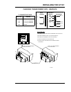
PROCEDURE
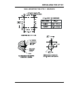
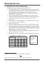
To rack mount the AT10.1, first install the brackets onto the rack. Second,
mount the AT10.1 onto the rack-mounting brackets using the hardware
supplied. Provide at least 6in / 152mm of air space above and below the
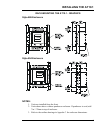
AT10.1 in the rack for cooling. You do not need to modify the AT10.1
enclosure. Rack-mount outline dimensions are shown on the next page.
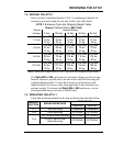
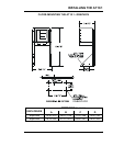
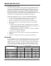
RACK WIDTH CHARGER RATING
Vdc Adc
19in / 483mm 23in / 584mm 24in / 610mm
12 Vdc all
Yes Yes Yes
24 Vdc all
Yes Yes Yes
48 Vdc 6-12 Adc
Yes Yes Yes
48 Vdc 16-25 Adc
No Yes Yes
130 Vdc 6 Adc
Yes Yes Yes
130 Vdc 12-25 Adc
No Yes Yes