


SERVICING THE AT10.1
52
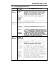
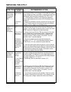
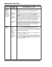
SYMPTOM
PROBABLE
CAUSE
RECOMMENDED ACTION
Front panel
dies during ac
power failure;
dc voltage is
present at
TB1
1. Defective
power resistor
R3
2. Defective
wiring
1. Use a dc voltmeter to measure the dc voltage from E17 on
the I/O panel to TB1(-). It is normally 12 Vdc when the rated
output voltage is at TB1(+) and TB1(-). Remove all power from
the charger, and measure the resistance from TB1(+) and
E17. See the table in section 3.6 for the proper resistance
values. If the resistance is not within 10% of the table value,
replace R3.
2. Remove the enclosure shroud, and check the wiring to and
from TB1 and the control circuit board for signs of insulation
damage or burns. Repair any damaged wiring.
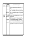
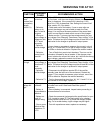
Charger
output
voltage too
high, not
controllable
1. Defective
SCR
2. R4 or R14 is
defective, or
wrong value
3. Defective
temperature
compensation
probe (optional)
4. Defective
control circuit
board A1
1. Disconnect wire # 24 from terminal E3 of the rectifier
assembly (near the left front of the enclosure). Restart the
charger. If You are able to measure output current, one of the
SCRs is defective. Replace the rectifier assembly.
2. Remove one end of R4 from TB5 (on the back of the front
panel). Repeat for R14 connected to TB1(-). Measure their
values with an Ohmmeter. See the table in section 3.6 for
resistance values. If either resistor is not within 1% of the
specified value, it must be replaced.
3. Remove the leads from the probe and measure its
resistance. At 77° F / 25° C the resistance should be about
10,000 Ohms. If it is not, replace the probe assembly.
4. If the front panel meter shows more than 110% of rated dc
current, the control board may be defective. Disconnect wire #
24 from terminal E3 of the rectifier assembly (near the left front
of the enclosure). Restart the charger. If the output current
goes to zero, replace the control board.
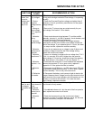
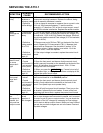
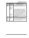
Output
voltage does
not agree
with front
panel meter
1. Temperature
compensation
probe is
installed
2. Circuit board
or another
component may
have been
replaced
3. R4 or R14 is
defective, or
wrong value
4. Defective
control circuit
board A1
1. If the optional temperature compensation probe is installed,
the output voltage may be different from the selected float or
equalize voltage. The difference in the voltages depends on
the probe temperature. The front panel meter always displays
the proper voltage for 77° F / 25° C.
2. Recalibrate meter as described in section 2.3.7.
3. Remove one end of R4 from TB5 (on the back of the front
panel). Repeat for R14 connected to TB1(-). Measure their
values with an Ohmmeter. See the table in section 3.6 for
resistance values. If either resistor is not within 1% of the
specified value, it must be replaced.
4. Turn off both front panel circuit breakers. Then turn on the
dc breaker, followed by the ac breaker. If the charger still has
the wrong output voltage, replace the control circuit board.