


OPERATING THE AT10.1
42
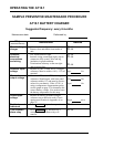
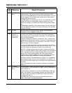
SAMPLE PREVENTIVE MAINTENANCE PROCEDURE
AT10.1 BATTERY CHARGER
Suggested frequency: every 6 months
Maintenance date Performed by
Step
(standard features)
Instructions Results
Clean battery
charger
• All vents clean and open.
• Remove dust and debris from inside of
unit.
o OK
o OK
Check all
electrical
connections
and wiring
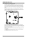
• TB1 connections all tight.
• Internal wiring connections tight, slip-on
connectors fully seated. Wire and lug
insulation in good condition.
• Terminations at battery or bus are tight
and corrosion free.
o OK
o OK
o OK
Check ac input
voltage
• Measure at TB1-L1 and TB1-L2 using ac
voltmeter. Must be within +10%, -12% of
nominal.
Input Vac
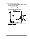
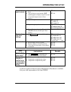
Check dc
output voltage
• Measure at TB1(+) and TB1(-) using dc
voltmeter. Should agree with front panel
voltmeter within 1%, and must be correct
values for your battery. If the AT10.1 is
using a temperature compensation probe,
see the graph on page 23 to determine the
correct battery voltage. You need to know
the battery temperature for this step.
Float Vdc
Equal. Vdc
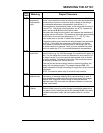
Check ripple
voltage
• Measure at battery terminals using ac
voltmeter set to millivolts scale. Check
against specification in Appendix A on
page 70.
Ripple mVac
Test font panel
indicators
• Press LAMP TEST key on front panel.
o OK
Test common
alarm relay
• Press LAMP TEST key and hold for 4
seconds. Common alarm relay will
transfer.
o OK