


ATCA-C110/1G Installation and Use Manual
Chapter 6 Memory Map and Registers
74
REVIEW COPY
I
2
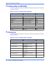
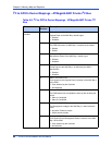
C Address Map for MPC8540
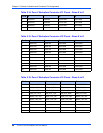
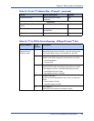
The devices supported by the Processor MPC8540 I
2
C interface along with their I
2
C addresses
are shown in Table 6-4.
I
2
C Resources
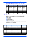
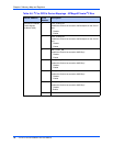
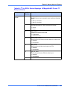
The Address Map for the I
2
C devices on the Private I
2
C interface for the Slave micro-controller
is shown in Table 6-5.
Table 6-4. Private I
2
C Address Map - MPC8540
Device Device description Address
Carrier Board Devices
Boot Sequencer Boot parameters for the MPC8540 0xA0
Onboard SPD SPD details for onboard devices 0xA2
SODIMM SPD SPD details for SODIMM devices 0xA4
PM8380 MUX for Fabric Interface 0XB2
PM8380 MUX for Fabric Interface 0XB4
RTC Real Time Clock 0xD0
PCI-Express Clock Buffer ICS9DB108 0xDC
FIM Devices
BCM56502/4 EEprom Default parameters for BCM Switch 0xA8
PM8380 SATA MUX 0xB0
Table 6-5. Private I
2
C Address Map - ATmega8L
Device Device description Address
Carrier Board Devices
BIB - EEPROM for Carrier Board Board Information Block EEPROM 0xA0
I
2
C to GPIO Device CLK2 Buffer enable control,
PCA9557PW.
0x3A
I
2
C to GPIO Device CLK1 Buffer enable control,
PCA9557PW.
0x38
I
2
C to GPIO Device CLK3 Buffer enable control,
PCA9557PW.
0x3C
I
2
C to GPIO Device Telecom Clock selection control,
PCA9557PW.
0x3E
Temperature Sensor Inlet Air Temperature Sensor,
TMP100
0x92
Temperature Sensor Outlet Air Temperature Sensor,
TMP100
0x96