


Chapter 1 ATCA-C110/1G Baseboard Preparation and Installation
ATCA-C110/1G Installation and Use Manual
13
REVIEW COPY
Step 2:Identify the AMC bay to be used for installation. Please note the following possibilities:
– If the required AMC bay is occupied by the AMC filler panel, you will need to remove the
filler panel before proceeding with the installation procedure. The handles’ latch
mechanisms for the filler panel and the AMC module are similar, follow the steps listed in
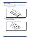
Removing an AMC Module from a Powered System on page 14 to remove the filler panel.
The blue LED on the filler panel is irrelevant.
– If the identified bay is already filled by another AMC module, remove this module from the
bay (follow the steps listed in Removing an AMC Module from a Powered System on page
14).
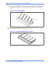
Step 3:Ensure that board handles are in the extracted position: pulled outward, away from the
faceplate.
Step 4:Using your thumb, apply equal and steady pressure on the faceplate as necessary to carefully
slide the AMC module into the guides rails.
Step 5:Continue to gently push the module along the guide rails till the module is fully engaged with the
connector. Avoid using excessive force during this operation.
Step 6:Wait for the blue LED to glow. The blue LED glows when the AMC module is completely
engaged with the connector.
Step 7:Press board handles inwards towards the faceplate to lock the AMC module on AMC bay.
Step 8:Wait for the blue LED to perform a series of long blinks. The blue LED blinks when the handles
are locked in position indicating module detection and activation by the carrier board.
Step 9:Observe blue LED status/activity. The module is fully installed when the blue LED stops blinking.
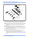
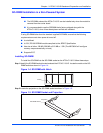
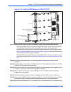
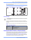
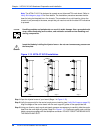
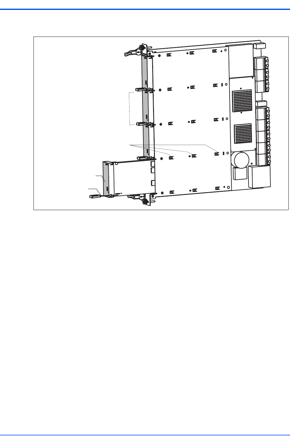
Figure 1-10. Installing AMC Module in ATCA-C110/1G
AMC Bay
AMC Module Handle
SIngle-Width, Full Height
AMC Module
Position of AMC Guide Rail
Anchoring Points