


ATCA-C110/1G Installation and Use Manual
Chapter 5 Controls, Indicators and Connector Pin Assignments
60
REVIEW COPY
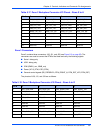
Clocks
The telecom synchronization clocks from LCCB interface are routed to the AMC boards. The
option for the AMC Module to drive the CLK3 to the ATCA backplane is provided for the AMC
Bay3 and AMC Bay4.
Common Options Region
The ATCA-C110/1G has two Gigabit Ethernet SerDes ports and two SATA ports on the
Common Options Region interface.
The Gigabit Ethernet SerDes ports from each AMC Bay are routed to the Fabric Interface
Module through the carrier board.
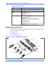
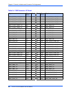
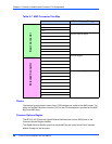
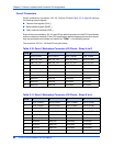
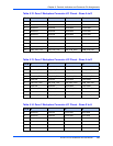
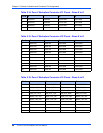
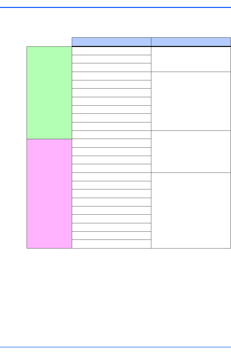
Table 5-7. AMC Connector Port Map
Port number AMC Port Mapping Strategy
CLKA Clocks
CLKB
CLKC
0 Common Options Region
1
2
3
4
5
6
7 Fat Pipes Region
8
9
10
11
12 Extended options Region
13
14
15
16
17
18
19
20
Basic ConnectorExtended Connector