


ATCA-C110/1G Installation and Use Manual
Chapter 1 ATCA-C110/1G Baseboard Preparation and Installation
22
REVIEW COPY
Step 1:Remove face plate cables and cables from the AMC, if applicable.
Step 2:Loosen the board's captive screws.
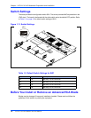
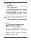
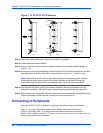
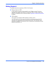
Step 3:Gently pull the top and bottom ejector handles outward from its locked position (Stage 2 of
Figure 1-14).
Step 4:Do not remove the board immediately. Wait for the blue LED first perform short blinks, and then
glow persistently. If the blue LED fails to respond refer to Appendix A, Troubleshooting.
Note Please wait for the blue LED to glow persistently before proceeding to the next step.
Unlatching this ejector lever will start the shutdown process on the blade. Software will
illuminate the blue hot swap LED on the faceplate when it is safe to remove the blade.
Step 5:Once the blue LED glows, gently pull handles outwards to disconnect the board from the
baokplane connectors. Continue to gently slide the board outwards along the guide rails.
Step 6:After board removal is complete, place the board on a clean and adequately protected working
surface (preferably an ESD mat) with the top side of the board facing up.
Connecting to Peripherals
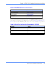
When the ATCA-C110/1G is installed in a shelf, you are ready to connect peripherals.
Figure 1-1 on page 3 depicts the location of the different connectors onboard the
ATCA-C110/1G and Table 1-4 on page 23 lists the different connectors onboard the
ATCA-C110/1G. Refer to Chapter 5, Controls, Indicators and Connector Pin Assignments, for
the pin assignments of the connectors.
Figure 1-14. ATCA-C110/1G Removal
Sta
g
e 2
Stage 3
Stage 1