Chapter 4 Functional Description
ATCA-C110/1G Installation and Use Manual
43
REVIEW COPY
Private I
2
C Bus
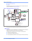
There are two private I
2
C busses implemented on the IPMI Module of ATCA-C110/1G. The
busses are Master-only I
2
C busses implemented on the Slave micro-controllers.
The private I
2
C Bus from the ATMega8 micro-controller has the following devices:
■ Board Information Block (BIB) EEPROM
Note The 64 kb Serial EEPROM contains the BIB (board Information block) data structure,
consisting of information such as the serial number of the board, MAC addresses of network
interfaces, variant information and some additional information. The EEPROM has an I
2
C
interface and is connected to the private I
2
C interface of the IPMC.
■ Two temperature sensors, which monitors the inlet and outlet air temperature of the board
and the onboard temperature sensor
■ The Telecom clock buffer-enable and the Telecom clock selection signals.
Payload Interface
The ATCA-C110/1G provides a UART interface intended for use as an interface to the host
(payload). The payload interface is implemented using the built-in USART1 controller of the
Master Controller of the IPMI Block. The ATCA-C110/1G boards are equipped with 8 MHz
clocks and provide reliable support for baud rates of up to 9600 on the payload interface. The
payload interface implements data lines (RXD1, TXD1) only.
8-bit Analog-to-Digital Converters (ADC)
The ADCs of the IPMI monitor the voltages on the ATCA-C110/1G. In addition to the voltages,
the current drawn by the payload from the Power module on the 12V rail and the temperature
of the Power module are also monitored. The current drawn by the AMC on the 12V and the
Management Power rail are measured by the IPMC using the ADCs of the micro-controller.
AMC Power Limiting Control
The IPMI management on the ATCA-C110/1G controls the power to the AMC module. The
power control block of the IPMI continuously monitors the payload power delivered to the AMC
module.
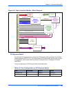
Telecom Clock Interface Control
The IPMI controls the telecom clock selection on ATCA-C110/1G, to provide the E-keying
support. The selected clock from the backplane is processed for jitter and then is fed to the AMC
bays and the RTM.
The clock selection logic also provides the option for AMC Bay 3 or AMC Bay 4 to drive a
reference clock signal to the backplane.


