


ATCA-C110/1G Installation and Use Manual
Chapter 1 ATCA-C110/1G Baseboard Preparation and Installation
8
REVIEW COPY
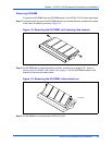
Step 3:After removing the carrier board from its card slot, place it on a clean and adequately protected
working surface (preferably an ESD mat) with the bottom side of the board facing up.
Step 4:Remove the screws from the holes in the carrier board that fasten the FIM to the carrier board.
Step 5:Carefully turn the carrier board over to the top side and place it on your working surface. Gently
separate the FIM from the FIM connectors on the carrier board. Do not damage or bend
connector pins.
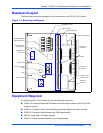
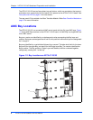
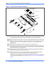
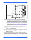
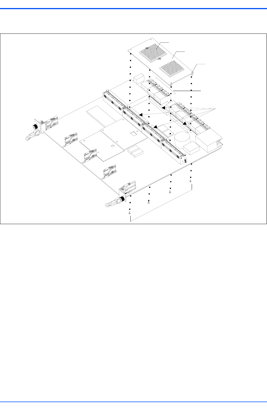
Step 6:Identify the FIM connectors on the carrier card as shown in the figure above.
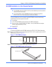
Step 7:Align the FIM over the FIM connectors making sure that the larger heatsink (with holding clips)
is oriented towards the Zone 3 connector. Ensure that the NPTH of the FIM is aligned with the
NPTH of the ATCA-C110/1G carrier board.
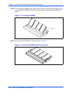
Step 8:Carefully press the FIM into the FIM connectors. Ensure that the standoffs of the module are
seated into the mounting holes of the carrier board.
Step 9:Turn the carrier board over and on the bottom side of the carrier board, fasten the screws
through the holes in the carrier board and the spacers. Tighten the screws.
The FIM is now fully installed on the carrier board. Install the ATCA-C110/1G in its proper card
slot by following the procedures given in Installing the ATCA-C110/1G in a Powered Chassis on
page 19.
Figure 1-3. Fabric Interface Module Installation
FIM Connectors
Screws
FIM Module
NPTH for keying
Zone 3 Connector
Copper Plated Heatsink
(with holding clips)