


ATCA-C110/1G Installation and Use Manual
Chapter 2 Operating Instructions
26
REVIEW COPY
■ Before the system is powered up ensure that chassis power supply voltage settings
matches the voltage present in country of use (if the power supply in your system is not
auto-sensing).
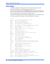
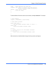
■ The initial U-Boot boot-up prompt (ATCA-C110>) is displayed on the console.
Hot Swap Support
The ATCA-C110/1G provides hardware to support the physical connection process and the
hardware connection process of the full hot swap system model defined in the PICMG 3.0
Specification.
The ATCA-C110/1G may be inserted and extracted from the system chassis while power is
applied. Hot swap circuitry protect the board from electrical damage.
Ejector Handles
The ejection handles’ switch is activated when the ejector handles are opened. The state of the
switch is monitored by the IPMC.
Indicator LEDs
The light-emitting diodes (LEDs) on the front panel are explained in Table 5-1 on page 52.
Booting with Firmware
Refer to Chapter 3, U-Boot Firmware Overview for details about U-Boot.
Reset Sources
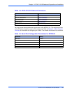
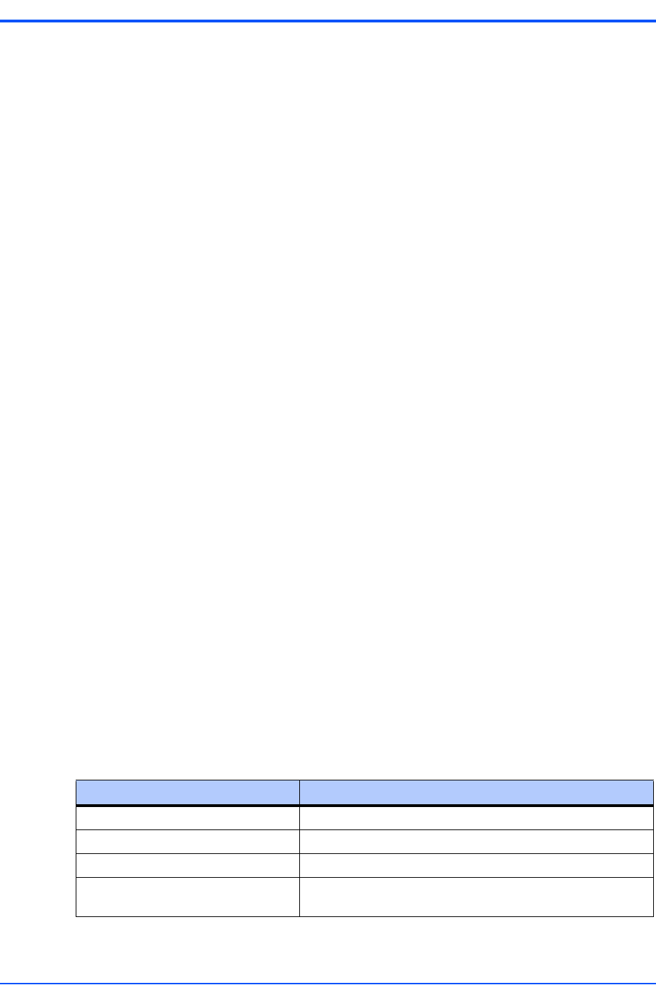
The ATCA-C110/1G provides reset control from various sources. Hard or soft resets may be
generated. A hard reset is defined as a reset of all onboard circuitry and reset of all onboard
peripheral devices. A soft reset is defined as a reset of the Processor. Table 2-1 describes each
reset source.
Each source of reset will result in a reset of the Processor, and all other onboard logic.
Table 2-1. Reset Sources
Reset Sources Description
Power-On Reset Reset during power-up
Power-bad reset generated onboard Reset signal generated when one of the voltage rails goes bad
IPMI Reset from IPMI
Rear Panel Reset (for debug
purposes only)
Manual Reset from ARTM-C110