


ATCA-C110/1G Installation and Use Manual
Chapter 4 Functional Description
42
REVIEW COPY
■ Telecom Clock Interface Control
■ Digital IO
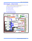
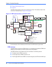
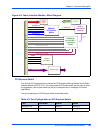
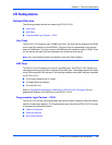
The IPMI module consists of three micro-controllers from Atmel. The interface of each of the
controllers is illustrated below in Figure 4-3 on page 42.
A brief description of the interfaces and the functions of the IPMI block are given below.
IPMB Interfaces
The IPMC Module provides three IPMB interfaces, two interfaces to the backplane (IPMB-A and
IPMB-B) and one interface to the AMC modules and the RTM (IPMB-L).
The IPMB interfaces are split between the micro-controllers in the following manner:
■ The Master has the IPMB-A connection,
■ The ATmega8 has the IPMB-B connection, and
■ The ATmega64-AMC has the IPMB-L connection that goes to the RTM and the AMC bays.
Figure 4-3. IPMI Implementation on ATCA-C110/1G
Carrier
LEDs
ATMega64-Master
ATMega8
ATMega64-AMC
SPI
(SCK, MISO, MOSI, SS#)
UART0 -
debug
console
Slave1_RDY_IRQ
Slave1_DATA_IRQ
Slave2_RDY_IRQ
Slave2_DATA_IRQ
E_PWR_EN
HANDLE_SW
RESET#
From debug port
8MHz
oscillator
Clock
buffer
HA[7:0]
I2C
buffer
IPMB-A
UART1 - payload
(service
processor)
communication
FRU_PWR_EN
Payload_Reset
(to Reset logic)
RESET#
RESET#
Slave_RST#
IPMB-B
Master-only I2C
UART -
debug
console
ADC
On-board voltages
UART1 -
debug
console
IPMB-L
4 x I2C
buffer
PP_EN
(to payload pwr controller)
MP_EN
(to mgmt pwr controller)
PP_PWRGD
(from payload pwr controller)
MP_PWRGD
(from mgmt pwr controller)
AMC_ENABLE#
AMC_PS1#
EEPROM
Temp.
sensors
ADC
Telecom Clock
Control
Payload current sense
I2C
buffer
Interrupts to
Payload