


Appendix C Thermal Validation
ATCA-C110/1G Installation and Use Manual
97
REVIEW COPY
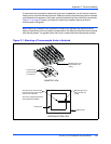
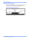
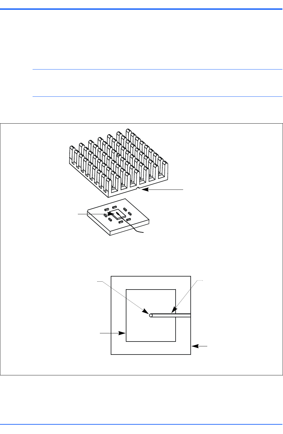
If components are covered by mechanical parts such as heatsinks, you will need to machine
these parts to route the thermocouple wire. Make sure that the thermocouple junction contacts
only the electrical component. Also make sure that heatsinks lay flat on electrical components.
Figure C-1 on page 97 shows one method of machining a heatsink base to provide a
thermocouple routing path.
Note Machining a heatsink base reduces the contact area between the heatsink and the
electrical component. You can partially compensate for this effect by filling the machined areas
with thermal grease. The grease should not come in contact with the thermocouple junction.
Figure C-1. Mounting a Thermocouple Under a Heatsink
HEATSINK BOTTOM VIEW
ISOMETRIC VIEW
Machined groove for
thermocouple wire
routing
Thermocouple
junction bonded
to component
Heatsink base
Thermal pad
Through hole for thermocouple
junction clearance (may require
removal of fin material)
Also use for alignment guidance
during heatsink installation
Machined groove for
thermocouple wire
routing