Chapter 4 Functional Description
ATCA-C110/1G Installation and Use Manual
47
REVIEW COPY
I/O Subsystems
Onboard Devices
The following onboard devices are present on ATCA-C110/1G
■ User Flash
■ AMC Bays
■ Programmable Logic Devices – CPLD
User Flash
The ATCA-C110/1G supports upto 128 MB User Flash. The User Flash is located on the GPCM
on the Local Bus Interface of the MPC8540. The User Flash is implemented in two physical
banks of 64 MB each. The device used is a 32 MB flash with a data bus width of 16 bits. There
are two devices per bank with two separated write-enables for each device.
Note Only word-aligned transfers are allowed on the User Flash interface.
AMC Bays
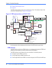
The ATCA-C110/1G supports up to four B+ type AMC bays. The ATCA-C110/1G supports a
centralized switching for the Fabric Interface on the AMC bays. The interface signals are routed
to the FIM through the FIM Connector. The following interfaces on the AMC bays are supported
by ATCA-C110/1G:
■ PCI-Express interface link of 4 lanes
■ 2x Gigabit Ethernet interface
■ 2x Serial ATA Link
Refer to Geographical addressing of AMC Bays on ATCA-C110/1G on page 82 for the
geographical address of the AMC bay on the ATCA-C110/1G.
Programmable Logic Devices – CPLD
The ATCA-C110/1G has one programmable logic device used to implement dedicated board-
specific functions and registers. The Programmable Logic onboard the ATCA-C110/1G is used
to implement the following functions:
■ Power-on Sequence
■ Reset Architecture
■ Boot ROM Selection


