


Chapter 5 Controls, Indicators and Connector Pin Assignments
ATCA-C110/1G Installation and Use Manual
63
REVIEW COPY
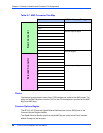
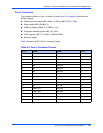
Zone 1 Connectors
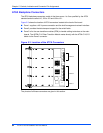
The connector residing in Zone 1 is called J10 (see Figure 5-3 on page 62) and carries the
following signals:
■ Power feed for the blade (ABP_VM48_x_CON and ABP_RTN_A_CON)
■ Power enable (ABP_ENABLE_x)
■ IPMB bus signals (APMB_P10_IPMB0_x_yyy)
■ Geographic address signals (ABP_P10_HAx)
■ Ground signals (ABP_P10_SHELF_GND and GND)
■ Reserved signals
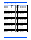
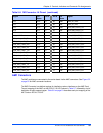
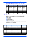
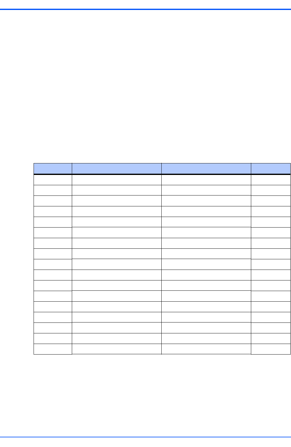
Table 5-9 shows the ATCA Zone 1 connector pinouts.
Table 5-9. Zone 1 Connector Pinouts
Pin # Signal Signal Pin #
1 Reserved Reserved 18
2 Reserved Reserved 19
3 Reserved Reserved 20
4 Reserved Reserved 21
5 HA0 Reserved 22
6 HA1 Reserved 23
7 HA2 Reserved 24
8 HA3 SHELF GND 25
9 HA4 LOGIC GND 26
10 HA5 ENABLE B 27
11 HA6 VRTN A 28
12 HA7 VRTN B 29
13 IPMB A SCL Reserved 30
14 IPMB A SDA Reserved 31
15 IPMB B SCL ENABLE B 32
16 IPMB B SDA -48V A 33
17 Reserved -48V B 34