


ATCA-C110/1G Installation and Use Manual
Chapter 1 ATCA-C110/1G Baseboard Preparation and Installation
18
REVIEW COPY
Understand Hot Swap
!
Caution
Caution
Board/Component Damage
Inserting or removing non-hot swap cards or transition modules with power applied
may result in damage to module components. Make sure that your blade manufacturer
identifies your module as hot swap ready.
The PICMG 3.0 Specification defines varying levels of hot swap. A blade that is compliant with
the specification can be inserted and removed safely with system power on without damage to
onboard circuitry. If a module is not hot swap compliant, you should remove power to the slot or
system before inserting or removing the module.
To facilitate hot swap, PICMG 3.0 specifies a blue LED on the face plate and board handles’
latch mechanism. This LED is under the control of System Management Firmware (IPMI).
The IPMI firmware will illuminate the blue hot-swap LED on the face plate, when it has powered
down the board, thus indicating that it is safe to remove the board.
!
Caution
ESD
Corruption of Data or File System
Powering down or removing a blade before the operating system or other software
running on the blade has been properly shut down may cause corruption of data or file
systems.
Therefore, ensure that the board has been properly shut down. You should ensure that
the blue hot swap LED on the faceplate is illuminated before extracting the module.
Refer to the Management chapter of the PICMG 3.0 Specification for more information about
hot swap
Control Elements
The ATCA-C110/1G provides the following elements as man-machine interface:
■ Injector/Ejector Lever and Hot Swap Switch Mechanism on page 18
■ Blue hot-swap LED (see Face plate and LEDs on page 51)
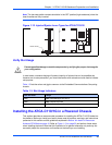
Injector/Ejector Lever and Hot Swap Switch Mechanism
The Hot Swap micro-switch is activated by the ATCA-C110/1G board ejector handles’
mechanism during the board insertion and extraction. This switch is used to confirm insertion
or to indicate a request for extraction to the IPMC.
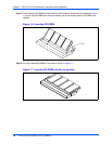
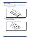
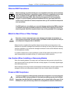
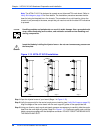
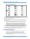
The following illustrations show the typical blade ejector handles used with the ATCA-C110/1G
payload cards. All handles are compliant with the AdvancedTCA specification and are designed
to meet the IEEE1101.10 standards. The handles facilitate insertion, locking and extraction of
the board. It includes the hot-swap micro-switch mounted on the board PCB. The board handles
are used to activate the micro-switch, which is the Hot Swap Switch, and to extract the board
by pulling it out of the ATCA slot from the chassis.