


Chapter 6 Memory Map and Registers
ATCA-C110/1G Installation and Use Manual
73
REVIEW COPY
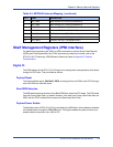
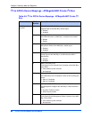
Shelf Management Registers (IPMI interface)
For details about accessing the IPMC via IPMI commands as well as Sensor Data Records
(SDRs) and Field Replaceable Unit (FRU) information provided by the blade, refer to the
ATCA-C110/1G Preliminary IPMI Reference Manual as listed in Appendix D, Related
Documentation.
Digital IO
The IPMI interface of the ATCA-C110/1G helps in the configuration and operations of the board
through its GPIO pins. They are listed as follows:
Payload Reset
The Payload Reset signal, PAYLOAD_RST#, is the signal from the IPMI to the CPLD through
which the IPMI can reset the board.
Boot ROM Selection
The IPMI determines the selection of the Boot ROM from which the CPU boots. The CPU boots
from the Primary Boot Flash, by default. However, if the boot from Primary Boot Flash fails, the
IPMC with the CPLD redirects the access to the Secondary Boot Flash.
Payload Power Enable
The Payload power of ATCA-C110/1G is controlled by the IPMI block, which enables or disables
the Payload power through the FRU_EN signal. This signal enables the power brick so as to
enable onboard conversion from -48V to 12V.
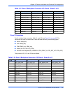
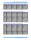
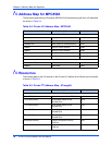
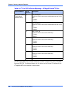
6 MPC_IRQ5 Base Interface PHY0 Interrupt (BCM5461S)
7 MPC_IRQ6 Base Interface PHY1 Interrupt (BCM5461S)
8 MPC_IRQ7 Processor TSEC PHY 1 (BCM5461S)
9 MPC_IRQ8 Processor TSEC PHY 2 (BCM5461S)
10 MPC_IRQ9 RTM PHY Interrupt (88E1145)
11 MPC_IRQ10 IPMI MPC interrupt 0 (ATMega64L-AMC)
12 MPC_IRQ11 IPMI MPC interrupt 1 (ATMega64L-AMC)
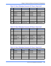
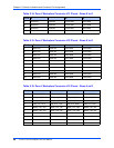
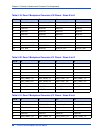
Table 6-3. MPC8540 Interrupt Mapping (continued)
Pin # NAME DESCRIPTION