


5
ATCA-C110/1G Installation and Use Manual
51
REVIEW COPY
5 Controls, Indicators and Connector Pin
Assignments
This chapter provides details of controls, indicators as well as connector pin assignments for all
connectors on the ATCA-C110/1G board.
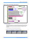
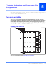
Face plate and LEDs
The ATCA-C110/1G has two face plates, top face plate and bottom face plate, which are
mounted to the top strut and bottom strut respectively. Top and bottom struts are mounted on
the main board using the corresponding mounting holes. Handles to extract the board, are
mounted to the main board using the mounting holes near the PCB edge. The following figure
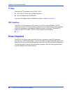
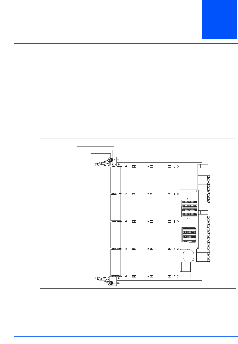
shows the LEDs available on the ATCA-C110/1G face plate.
The LEDs are described on table Face Plate LEDs on page 52:
Figure 5-1. Face plate LEDs
USR2
USR1
OOS
H/S