


ATCA-C110/1G Installation and Use Manual
Chapter 1 ATCA-C110/1G Baseboard Preparation and Installation
12
REVIEW COPY
Installing an AMC Module in a Powered System
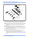
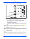
To install an AMC Module on a AdvancedTCA host board, refer to the Figure 1-10 on page 13,
read all cautions and warnings and perform the following steps. This figure is for reference only
and may not represent the exact host board you are using.
Note
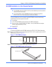
■ ATCA-C110/1G can accommodate up to four single-width, full-height, B+ Connector
Type, Advanced Mezzanine Cards. Refer to AMC Bay Locations on page 4 for the
locations of the AMC Bays onboard the ATCA-C110/1G.
■ The AMC installation procedure assumes that the ATCA-C110/1G is already installed
in its host chassis - see Installing the ATCA-C110/1G in a Powered Chassis on page 19.
■ The installation procedure assumes that the AMC module is being hot-inserted into a
live carrier. The procedure for a cold insertion (when the carrier is not powered) is the
same, except that you need not wait for the blue LED indications to proceed. For more
details about hot swap, refer to Understand Hot Swap on page 18.
■ Figure 1-10 on page 13 is for reference only and may not represent the exact carrier
board you are using.
■ Refer to the PrAMC-7201 Installation and Use manual as mentioned in Appendix D,
Related Documentation for more details.
Warning
Warni ng
Dangerous voltages, capable of causing death, are present in this equipment. Use
extreme caution when handling, testing and adjusting.
!
Caution
Caution
Damage of Circuits
Electrostatic discharge and incorrect board installation and removal can damage
circuits or shorten their life.
Therefore, before touching boards or electronic components, make sure that you are
working in an ESD-safe environment.
!
Caution
Caution
Module damage
Only mount permitted combinations of AMC variants. Otherwise, damage to AMC
module, carrier card and equipment attached to the rear transition board may occur.
Therefore, only install and use the AMC module together with the Embedded
Communications Computing’s carrier card.
Step 1:Attach an ESD strap to your wrist. Attach the other end of the ESD strap to the chassis as a
ground. The ESD strap must be secured to your wrist and to ground throughout the procedure.