


ATCA-C110/1G Installation and Use Manual
Chapter 6 Memory Map and Registers
80
REVIEW COPY
I
2
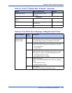
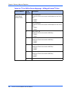
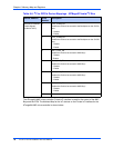
C to GPIO’s Device Mappings - ATMega64-AMC Private I
2
C Bus
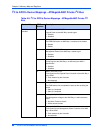
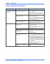
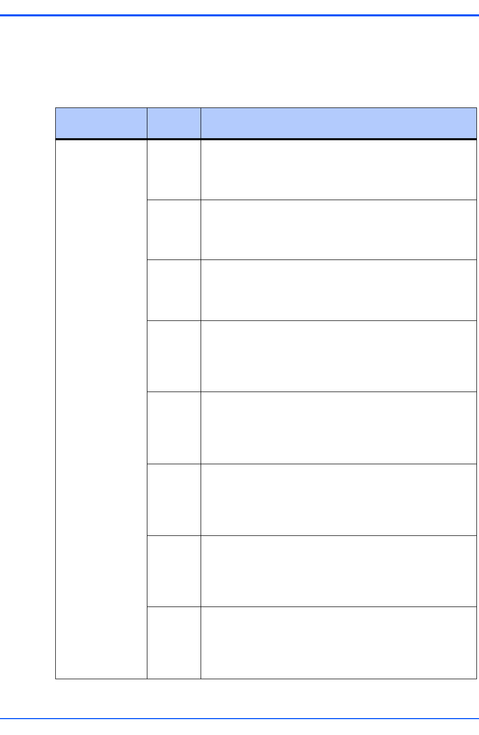
Table 6-8. I
2
C to GPIO’s Device Mappings - ATMega64-AMC Private I
2
C
Bus
Device Address GPIO
Number
Description
AMC Bay x Control
Interface
0 AMCx_PAYLOAD_PWR_EN#
Payload Power to the AMC Bay1 enable signal
0 - Enabled
1 - Disabled
1 AMCx_IMPB_EN
The IPMB Connection to AMC Bay x is enabled at the Isolator
0 - Disable
1 - Enable
2 AMCx_MGMT_PWR_EN#
Management Power to the AMC Bay x enable signal
0 - Enabled
1 - Disabled
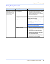
3 AMCx_EN#
Enable signal to the AMC Bay x, as defined by the AMC.0
Specification
0 - Enabled
1 - Disabled
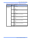
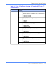
4AMCx_PAYLOAD_FLT#
Fault signal from the Payload Power Controller of the AMC Bay x
to the IPMC
0 - Fault asserted by the Controller
1 - Not Asserted
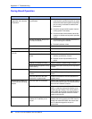
5 AMCx_IMPB_RDY
The IPMB isolator has completed the start-up after enabling the
device
0 - Start-up Completed
1 - Start-up Completed
6 AMCx_MGMT_PWRGD
The Management voltage to the AMC Bay x is within tolerance
levels
0 - Not within Tolerance Levels
1 - Within tolerance levels
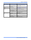
7 AMCx_MGMT_FLT#
Fault signal from the Management Power Controller of the AMC
Bay x to the IPMC
0 - Fault asserted by the Controller
1 - Not asserted