


Chapter 1 ATCA-C110/1G Baseboard Preparation and Installation
ATCA-C110/1G Installation and Use Manual
3
REVIEW COPY
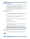
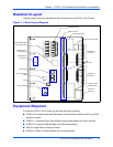
Baseboard Layout
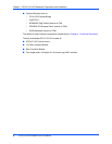
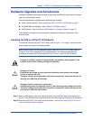
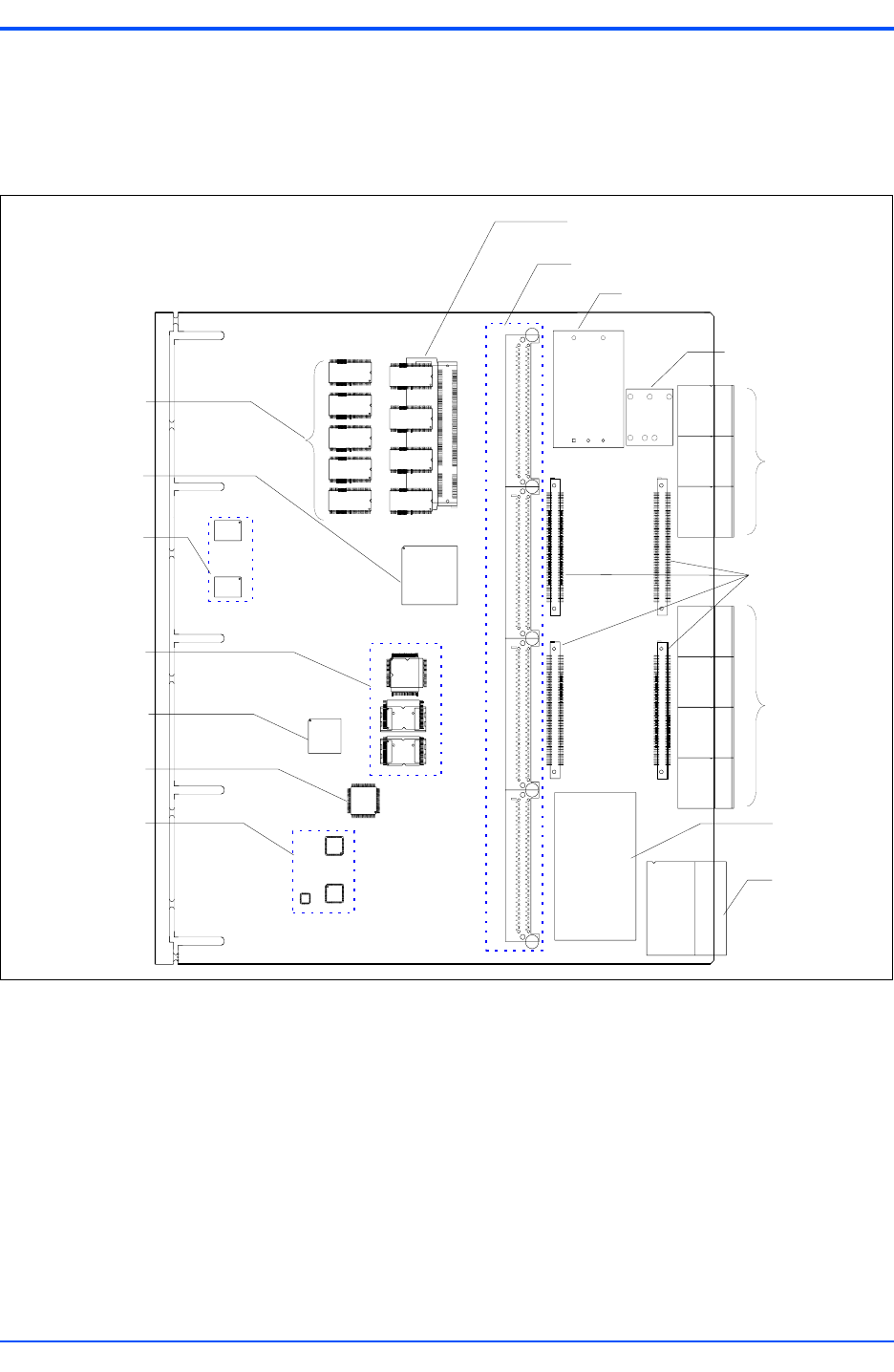
The figure below shows the placement of the components on the ATCA-C110/1G board.
Equipment Required
To install the ATCA-C110/1G board you need the following equipment:
■ PICMG 3.0 Compliant AdvancedTCA Modular Communications Platform AXP or any ATCA
complaint chassis
■ PICMG 3.1 Compliant Fabric Switch Blades supporting the Base and Fabric Interface
■ PICMG 3.0 Compliant Shelf Manager with IPMI interoperability
■ AMC B+ single-width, full-height modules
■ ARTM-C110 Rear Transition Module and connecting cables
Figure 1-1. Board Layout Diagram
Onboard DDR SDRAM
devices (bottom side)
SO-DIMM Connector
AMC Connectors
Payload Power Brick
Management Power Bric
k
ATCA Zone 3
Connectors
ATCA Zone 2
Connectors
ATCA Zone 1
Connector
FIM
Connectors
PowerQUICC III™
Microprocessor
Gigabit Ethernet
PHY devices
Flash Devices
PCI to PCI-Express
Bridge
CPLD
IPMI Controllers
J41
J40
J39
J38
J30
J31
J32
J20
J21
J22
J23
J1
J2
J4
J3
Hot Swap Control
and Holdup Cap