


ATCA-C110/1G Installation and Use Manual
Chapter 4 Functional Description
44
REVIEW COPY
Digital IO
The IPMI interface of the ATCA-C110/1G helps in the configuration and operations of the board
through its GPIO pins.
Refer to Digital IO on page 73 for more details about the GPIO pin signals.
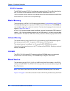
Fabric Interface Module
The FIM is used for high-speed differential signaling and performs switching functions for fabric
links. There are four FIM connectors onboard the ATCA-C110, each supporting 36 differential
pairs. The location of the FIM onboard the ATCA-C110/1G is shown in Figure 4-1 on page 37
The following interfaces are provided through the FIM connectors:
■ Fabric signals
– PCI-Express
– Gigabit Ethernet
–XAUI
– SATA Multiplexer
■ Power (3.3V, 12V, 5V, 3.3V Management)
■ Reset signals
■ Interrupt signals (from FIM devices to the base-board Service Processor)
■ I
2
C signals
■ Other control signals
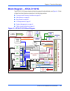
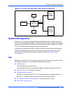
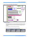
Block Diagram – FIM
The functional blocks of the FIM are illustrated in Figure 4-4 on page 45 and are described in
the following sections:
■ PCI-Express Switch
■ PCI-Express to PCI Bridge
■ Ethernet Switching Fabric
■ SATA Multiplexer
■ I2C Bus Interface