


ATCA-C110/1G Installation and Use Manual
Chapter 1 ATCA-C110/1G Baseboard Preparation and Installation
20
REVIEW COPY
Note The ATCA-C110/1G is designed to operate as an AdvancedTCA node board. Refer to
Verify Slot Usage on page 19 for more details. The installation procedure assumes that the
board is being hot-inserted into a live chassis. The procedure for a cold insertion (when the
chassis is not powered) is the same, except that you need not wait for the blue LED indications
to proceed.
Use ESD
Wrist Strap
ESD
Handling modules and peripherals can result in static damage. Use a grounded wrist
strap, static-dissipating work surface, and antistatic containers when handling and
storing components.
!
Caution
Caution
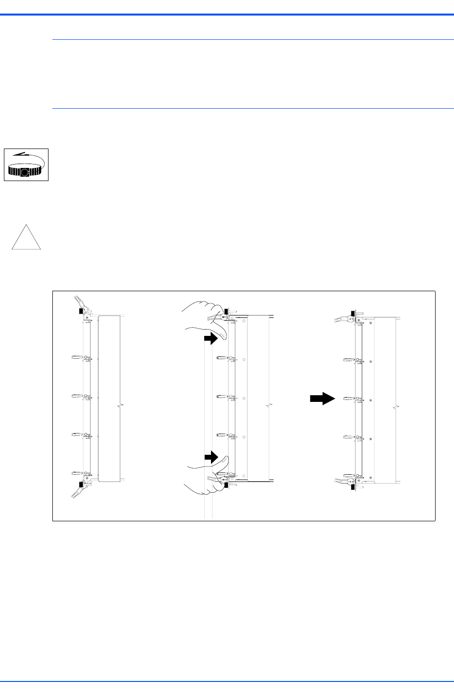
Insert the blade by holding the injector levers—do not exert unnecessary pressure on
the face plate.
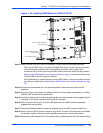
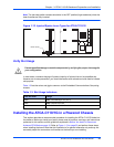
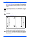
Step 1:Open the injector levers of your board (Stage 1 in Figure 1-13).
Step 2:Verify the proper slot for the carrier board you are inserting (see Verify Slot Usage on page 19).
Align the edges of the carrier board with the card cage rail guides in the appropriate slot.
Step 3:Using your thumbs, apply equal and steady pressure as necessary to carefully slide the carrier
board into the card cage rail guides (Stage 2 in Figure 1-13). Continue to gently push until the
blade connectors engage with the backplane connector. DO NOT FORCE THE BOARD INTO
THE BACKPLANE SLOT.
Figure 1-13. ATCA-C110/1G Installation
Sta
g
e 1 Sta
g
e 2 Sta
g
e 3