


Chapter 5 Controls, Indicators and Connector Pin Assignments
ATCA-C110/1G Installation and Use Manual
61
REVIEW COPY
The SATA ports are mapped to the Port 2 and Port 3 of the AMC connector as per the AMC.3
Specification. The ports from each of the AMC Bays are routed to the Fabric Interface Module.
Fat Pipes Region
The Fat Pipes Region in the ATCA-C110/1G is used for the x4 PCI-Express link from the AMC
cards to the PCI-Switch on the FIM.
Note The AMC.1 Specification defines a Control and Management x1 PCI-Express interface
for the Type-P AMC Modules. This interface is not supported on the ATCA-C110/1G board.
Extended Options Region
Note The Extended Options Region of the AMC Bay is not used on ATCA-C110/1G. and is
meant for debug purposes only.
This option is used to define Non-LVDS signals to or from the AMC. The AMC POST code
information is serialized and is given to the AMC carrier, which is decoded by the Programmable
Logic and this drives the LEDs on the ATCA carrier.
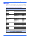
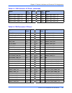
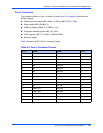
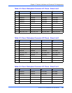
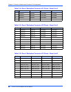
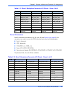
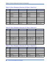
Table 5-8. AMC Connector Port Mapping on ATCA-C110/1G
Port number AMC Port Mapping on ATCA-C110/1G
CLKA CLK1
CLKB CLK2
CLKC CLK3/PCIe CLK
0 GbE SerDes PORT 1
1 GbE SerDes PORT 2
2 SATA PORT 1
3 SATA PORT 2
4 PCIe LINK 0 LANE 1
5 PCIe LINK 0 LANE 2
6 PCIe LINK 0 LANE 3
7 PCIe LINK 0 LANE 4
8-17 NC
18 Serial port interface (debug only)
19 Serial port and USB interface (debug only)
20 Postcode signals (for debug - Bay 4 only)