


ATCA-C110/1G Installation and Use Manual
Chapter 5 Controls, Indicators and Connector Pin Assignments
62
REVIEW COPY
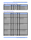
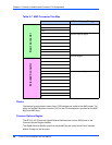
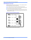
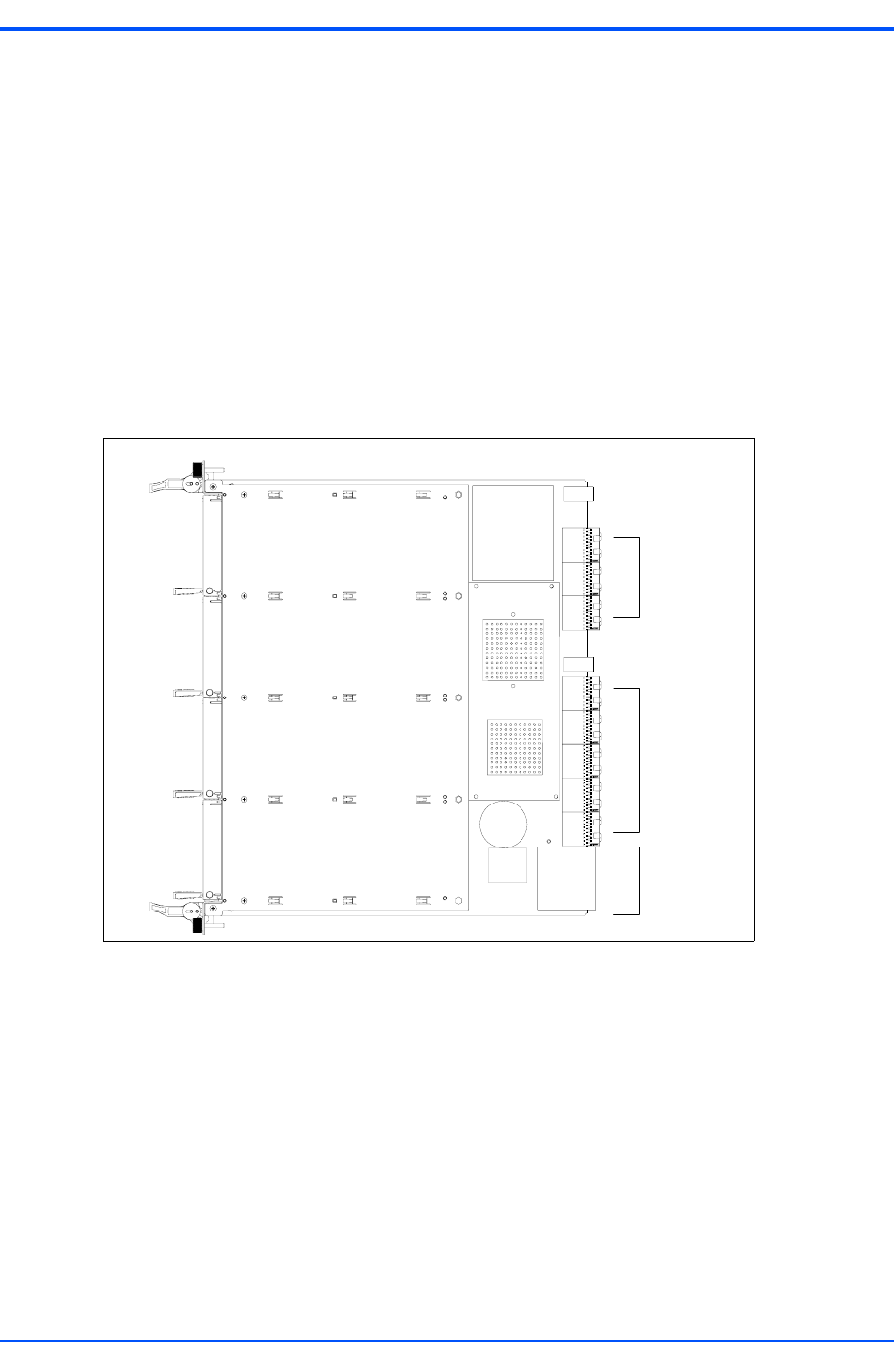
ATCA Backplane Connectors
The ATCA backplane connectors reside in the three zones 1 to 3 as specified by the ATCA
standard and are called J10, J20 to J23 and J30 to J31.
Figure 5-3 shows the location of ATCA connectors located at the back of the board.
■ Zone 1 supplies a -48-V power connection and the shelf-management network interface.
■ Zone 2 provides the data transport support for the switch fabric.
■ Zone 3 is for the rear transition modules (RTM) to handle cabling to devices on the main
boards. The ARTM-C110 Rear Transition Module mates directly with the ATCA-C110/1G
blade via the Zone 3 connector.
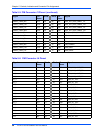
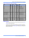
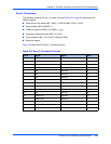
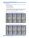
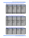
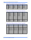
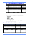
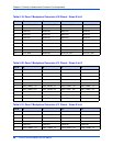
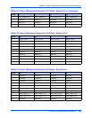
The pinouts of all these connectors are given in this section.
Figure 5-3. Location of the ATCA Connectors
Zone 1
Zone 2
Zone
3
J 10
J24
J23
J22
J22
J21
J30
J31
J32