


ATCA-C110/1G Installation and Use Manual
Chapter 5 Controls, Indicators and Connector Pin Assignments
52
REVIEW COPY
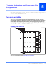
Baseboard Connectors
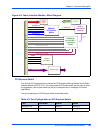
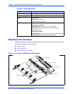
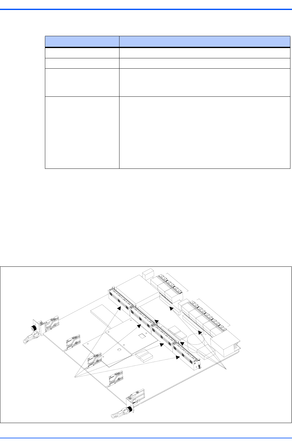
The following sections describe the onboard connectors on ATCA-C110/1G base board. Figure
5-2 shows the location of the connectors.
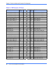
■ FIM Connectors
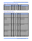
■ AMC Connectors
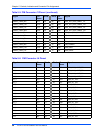
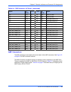
■ ATCA Backplane Connectors
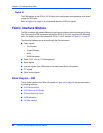
Table 5-1. Face Plate LEDs
LED Label Description
USR1 User LED 1
USR2 User LED 2
OOS Out Of Service
Red: Blade out of service
OFF: Blade working properly
HS FRU State Machine
During blade installation
Non-blinking blue: Powering up of on-board IPMC
Blinking blue: Blade communication with shelf manager
OFF: Blade is active
During blade removal
Blinking blue: Blade notification to shelf manager for deactivation
Non-blinking blue: Blade is ready to be extracted
Figure 5-2. Location of Baseboard Connectors
FIM Connectors
AMC Connectors
Zone 3 Connectors
Zone 3 Connectors
Zone 1 Connecto
r