


ATCA-C110/1G Installation and Use Manual
Chapter 1 ATCA-C110/1G Baseboard Preparation and Installation
4
REVIEW COPY
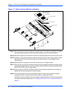
The ATCA-C110/1G has two face plates: top and bottom, which are mounted on the top strut
and bottom strut, respectively. No front panel I/O is present on the ATCA-C110/1G board. See
Face plate and LEDs on page 51 for more details.
The rear panel I/O is provided via a Rear Transition Module. Refer Rear Transition Modules on
page 15 for more information.
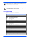
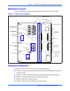
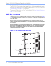
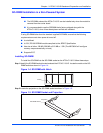
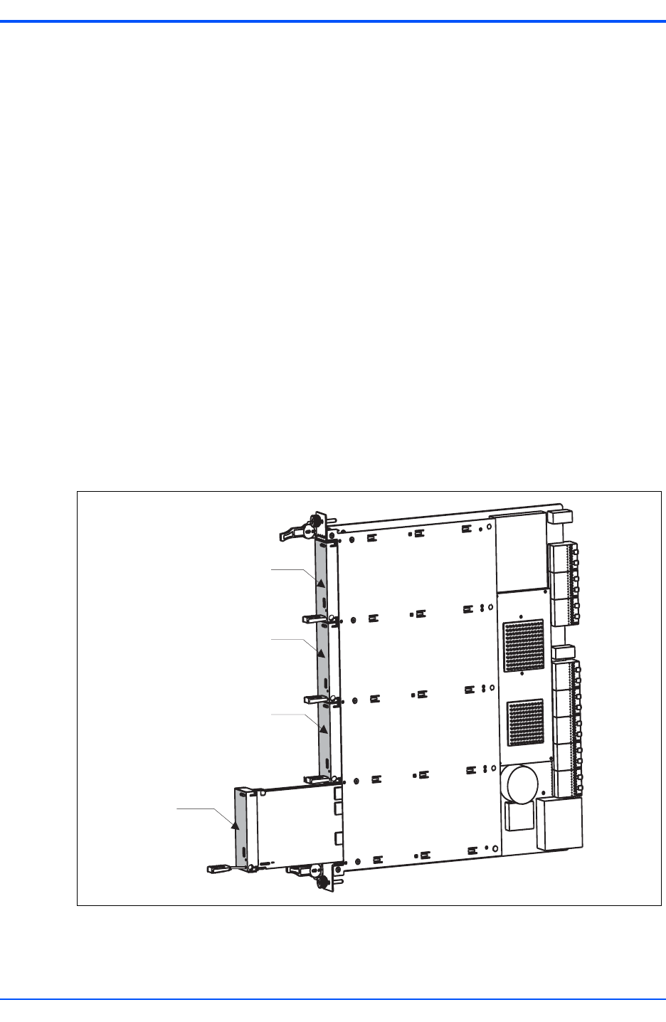
AMC Bay Locations
The ATCA-C110/1G is a conventional AMC carrier board with four B+ type AMC bays. Figure
1-2 shows AMC Bay locations on the ATCA-C110/1G board. An AMC Bay is a single AMC site
on an AMC carrier.
Bays on a carrier are identified by an alphanumeric value representing the Bay layer and
position. Bay layers are designated as A and B, while positions within each layer are designated
as 1 through 4.
Bays are identified by a capital letter followed by a numeral. The letter shall be A for the lower
Bay and B for the upper Bay, and also B for the Single Layer Bay. The number identifies the
Bay's position. The Bay positions, Single Layer and Stacked, shall be numbered together,
contiguously, starting with 1 at the top.
‘
Figure 1-2. Bay Locations on ATCA-C110/1G
B1
B2
B3
B4