


Chapter 1 ATCA-C110/1G Baseboard Preparation and Installation
ATCA-C110/1G Installation and Use Manual
19
REVIEW COPY
Note The hot-swap switch contacts should be in the OFF position (high-resistance) when the
board handles are fully inserted.
Verify Slot Usage
!
Caution
ESD
Prevent possible damage to module components by verifying the proper slot usage for
your configuration.
In most cases, connector keying will prevent insertion of a board into an incompatible slot.
However, as an extra precaution, you should be familiar with colored card rails used to indicate
slot purpose.
Table 1-3 lists the colors and glyphs common to the Embedded Communications Computing
chassis.
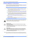
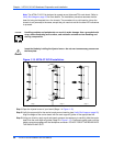
Installing the ATCA-C110/1G in a Powered Chassis
This section describes a recommended procedure for installing the ATCA-C110/1G blade into
the platform. Before you install your board, please read all cautions, warnings, and instructions
presented in this section and the guidelines explained in Before You Install or Remove an
AdvancedTCA Blade on page 16. Refer to Figure 1-13 on page 20 and perform these steps
when installing the board. Note that this illustration is for general reference only and may not
accurately depict the connectors and handles on the board you are installing.
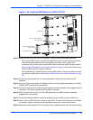
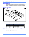
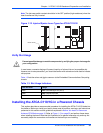
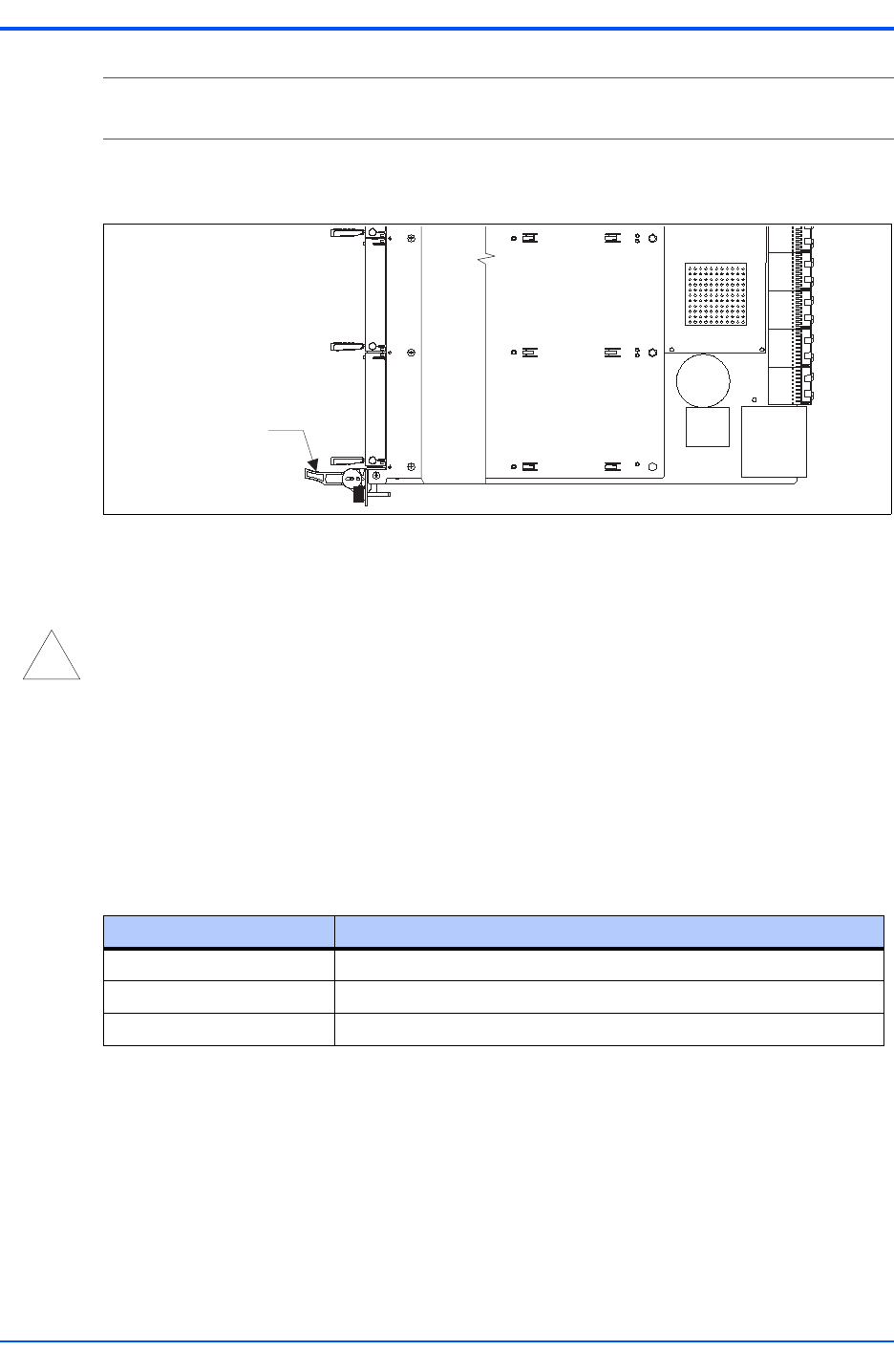
Figure 1-12. Injector/Ejector Lever Types for ATCA-C110/1G
Board Handle
Table 1-3. Slot Usage Indicators
Card Rail Color Usage
Black AXP: Shelf Manager slot (slot 0)
Black AXP: Payload Card slot
Red AXP: Controller Switch Card slot