


Appendix B Specifications
ATCA-C110/1G Installation and Use Manual
91
REVIEW COPY
Power Requirements
The blade’s power requirements depend on the installed hardware accessories. If you want to
install accessories on the board, the load of the respective accessory has to be added to that
of the blade.
In the following table you will find typical examples of power requirements with and without
accessories installed. For information on the accessories’ power requirements, refer to the
documentation delivered together with the respective accessory or consult your local Motorola
representative for further details.
The blade must be connected to a TNV-2 or a safety-extra-low-voltage (SELV) circuit.
Note A TNV-2 circuit is a circuit whose normal operating voltages exceed the limits for a SELV
circuit under normal operating conditions, and which is not subject to over voltages from
telecommunication networks.
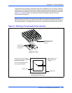
The power to the FIM is supplied via the pins of the FIM Connector. Three main voltages are
fed through the FIM Connector to the FIM board: 12V, 5V, 3.3V and 3.3V Management Power.
Other voltages required are derived on the FIM board.
The blade provides two independent power inputs according to the AdvancedTCA
Specification. Each input has to be equipped with an additional fuse of max. 90A located either
in the shelf where the blade is installed or the power entry module (PEM).
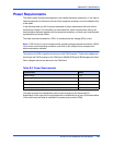
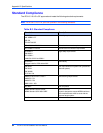
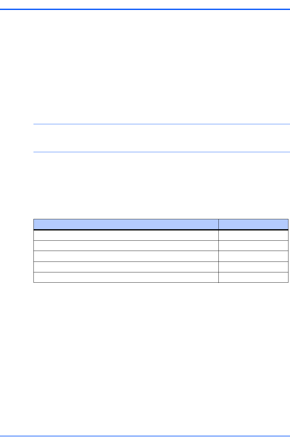
Table B-2. Power Requirements
Characteristic Value
Rated Voltage TBD
Operating Voltage TBD
Max. current TBD
Max. total power consumption of all four AMC sites TBD
Max. total power consumption of all installed blade accessories (AMCs) TBD