


ATCA-C110/1G Installation and Use Manual
Chapter 6 Memory Map and Registers
72
REVIEW COPY
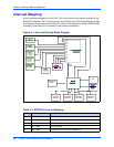
Interrupt Mapping
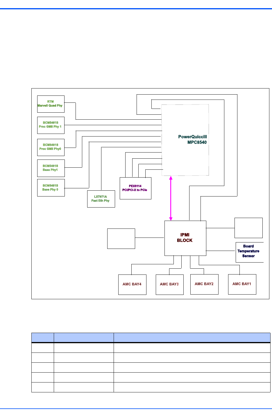
All the interrupts generated on the ATCA-C110/1G are wired to the interrupt controller of the
MPC8540 Processor. The PCI interrupts from the PCI/PCI-X to PCI-Express Bridge, the GbE
Phy interrupts and the interrupt from the DPLL of the LCCB interface are wired to the MPC8540
Processor. Given below is an illustration of the interrupt architecture.
Figure 6-1. Interrupt Routing Block Diagram
PS1#
PS1#
PS1#
PS1#
Telcom Clock
DPLL
RTM
INT0#
INT1#
INT2#
INT3#
INT4#
INT5#
INT6#
INT7#
INT8#
INT9#
INT10#
INT11#
Payload
Interface
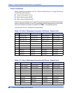
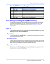
Table 6-3. MPC8540 Interrupt Mapping
Pin # NAME DESCRIPTION
1 MPC_IRQ0 8114 PCI IRQ0
2 MPC_IRQ1 8114 PCI IRQ1
3 MPC_IRQ2 8114 PCI IRQ2
4 MPC_IRQ3 8114 PCI IRQ3
5 MPC_IRQ4 Fast Ethernet PHY interrupt (BCM5461S)