


8 - 40
– +
ELEC
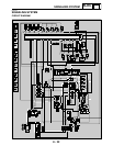
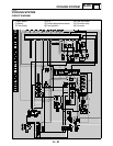
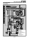
SIGNALING SYSTEM
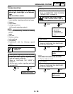
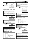
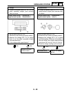
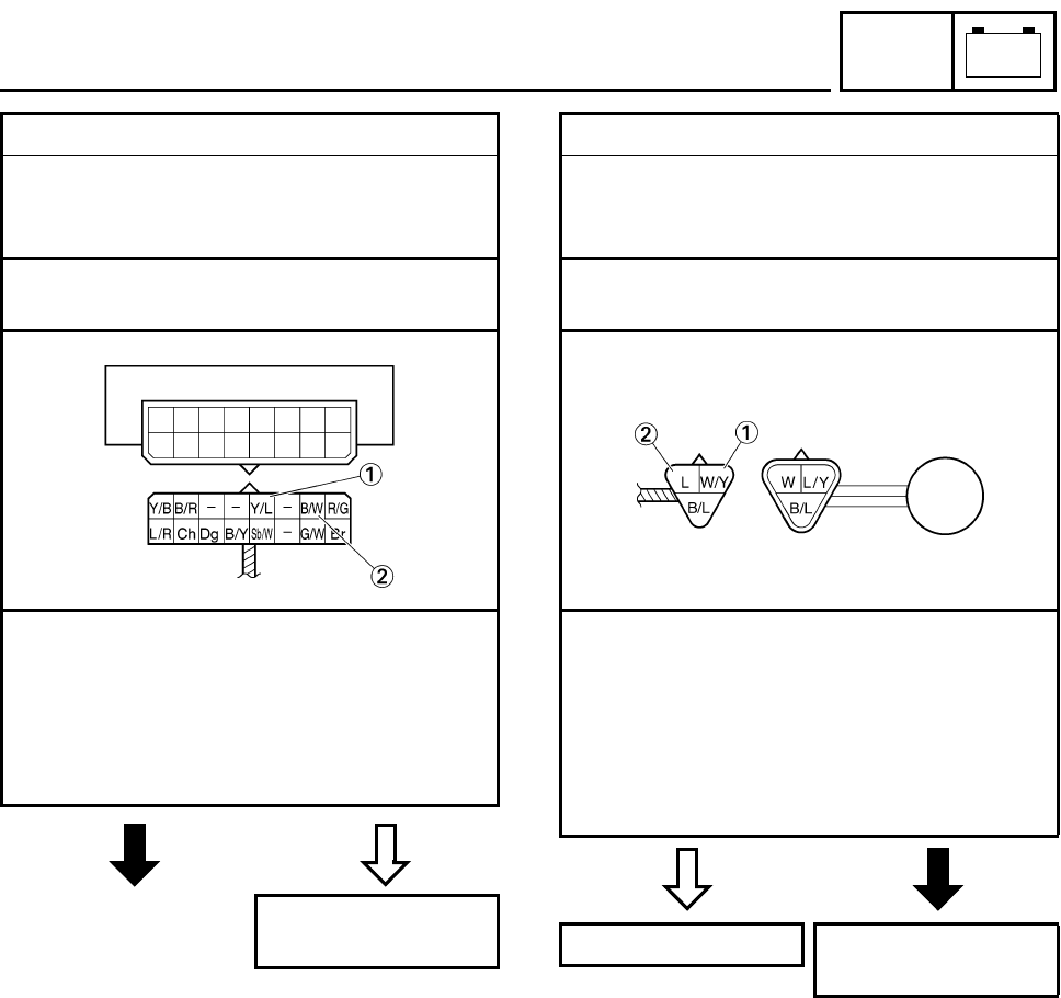
2. Voltage
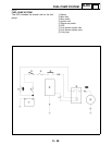
• Connect the pocket tester (DC 20 V) to the
meter assembly coupler (wire harness
side) as shown.
Positive tester probe
→
yellow/blue
1
Negative tester probe
→
black/white
2
• Set the main switch to “ON”.
• Elevate the rear wheel and slowly rotate it.
• Measure the voltage (DC 5 V) of yellow/
blue 1 on the meter assembly coupler
(wire harness side).
• Is the voltage within specification?
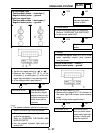
NO
YES
Replace the multi-
function meter.
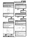
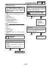
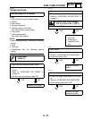
3. Speed sensor
• Connect the pocket tester (DC 20 V) to the
speed sensor coupler (wire harness side)
as shown.
Positive tester probe
→
white/yellow
1
Negative tester probe
→
blue
2
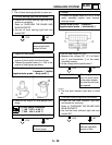
• Set the main switch to “ON”.
• Elevate the rear wheel and slowly rotate it.
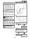
• Measure the voltage (DC 5 V) of yellow
and black/yellow. With each full rotation of
the rear wheel, the voltage reading should
cycle from 0.6 V to 4.8 V to 0.6 V to 4.8 V.
• Does the voltage reading cycle correctly?
YES
NO
This circuit is OK. Replace the speed
sensor.