


1 - 6
GEN
INFO
FEATURES
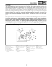
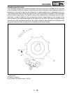
• Ignition control
The ignition control function of the ECU controls the ignition timing and the duration of ignition
energizing. The ignition timing control uses the signals from the throttle position sensor (to detect
the angle of the throttle), and the crankshaft position sensor and speed sensor (to detect the
speed of the engine). This control establishes an ignition timing that suits the operating condition
of the engine through compensations made to the basic ignition timing control map. The ignition
energizing duration control establishes the energizing duration to suit the operating conditions by
calculating the energizing duration in accordance with the signal received from the crankshaft
position sensor and the battery voltage.
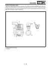
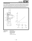
• Fuel control
The fuel control function of the ECU controls the injection timing and injection duration. The injec-
tion timing control controls the injection timing during the starting of the engine and the injection
timing during the normal operation of the engine, based on the signals received from the crank-
shaft position sensor and the cylinder identification sensor. The injection duration control deter-
mines the duration of injection based on the signals received from the atmospheric pressure
sensors, temperature sensors, and the position sensors, to which compensations are made to suit
various conditions such as the weather, atmospheric pressure, starting, acceleration, and deceler-
ation.
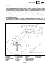
• Load control
The ECU effects load control in the following manner:
1. Stopping the fuel pump and injectors when the motorcycle overturns
The ECU turns OFF the fuel injection system relay when the lean angle cut-off switch is oper-
ated.
2. Operating the headlight illumination relay
The ECU controls the headlight relay 2 in accordance with the engine speed as required by the
daytime illumination specification.
3. Operating the radiator fan motor in accordance with the coolant temperature
The ECU controls the radiator fan motor relay ON/OFF in accordance with the coolant temper-
ature.
4. Operating the AI system solenoid valve
The ECU controls the energizing of the solenoid valve in accordance with the driving condi-
tions.
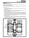
• Self-diagnosis function
The ECU is equipped with a self-diagnosis function to ensure that the engine control system is
operating normally. The ECU mode functions include a diagnosis mode in addition to the normal
mode.
Normal mode
• To check for any blown bulbs, this mode illuminates a engine trouble warning light while the
main switch is turned ON, and while the starter switch is being pressed.
• If the starting disable warning is activated, this mode alerts the rider by blinking the engine trou-
ble warning light while the start switch is being pressed.
• If a malfunction occurs in the system, this mode provides an appropriate substitute characteristic
operation, and alerts the rider of the malfunction by illuminating an engine trouble warning light.
After the engine is stopped, this mode displays a fault code on the clock LCD.
Diagnosis mode
• In this mode, a diagnostic code is input into the ECU through the operation of the operating
switch on the meter, and the ECU displays the values output by the sensors or actuates the
actuators in accordance with the diagnostic code. Whether the system is operating normally can
be checked by observing the illumination of the engine trouble warning light, the values dis-
played on the meter, or the actuating state of the actuators.