


8-2
hsb
2
PLUS Series LCD Display
Planning the
Installation
Note: If you wish to practice using the display before installation, connect a
12V or 24V DC power supply (connecting the red wire via a 6.3A quick blow
fuse to positive and the black wire to negative) and using the simulator mode,
as described in Chapter 2.
For full functionality of the radar and chartplotter you need to provide position
and heading data.
• Orientation - heading data is required for the radar to operate in North Up
and Head Up mode and the chart to operate in Course Up and Head Up.
• MOB requires heading and speed data. Alternatively, SOG and COG
(derived from the same source as position data) enable the MOB function.
• MARPA requires accurate heading data; full MARPA functionality is pro-
vided if SOG and COG are also available.
• Position data is required for full functionality of the chart display.
Full details of heading, position and other data are given in Section 8.8.
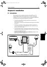
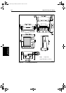
Planning the Installation
Before you install your system, plan the installation, considering:
• Location of the display unit, as described in Section 8.3
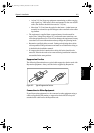
• Cable Runs, including cables for an integrated system (to provide heading
and position data etc.), as described in Section 8.4.
EMC Installation Guidelines
All Raymarine equipment and accessories are designed to the best industry
standards for use in the recreational marine environment.
Their design and manufacture conforms to the appropriate Electromagnetic
Compatibility (EMC) standards, but correct installation is required to ensure
that performance is not compromised. Although every effort has been taken to
ensure that they will perform under all conditions, it is important to understand
what factors could affect the operation of the product.
The guidelines given here describe the conditions for optimum EMC
performance, but it is recognized that it may not be possible to meet all of these
conditions in all situations. To ensure the best possible conditions for EMC
performance within the constraints imposed by any location, always ensure
the maximum separation possible between different items of electrical
equipment.
For optimum EMC performance, it is recommended that wherever possible:
• Raymarine equipment and cables connected to it are:
81186_2.book Page 2 Monday, December 17, 2001 8:35 AM