


Chapter 8: Installation 8-13
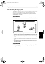
Display Unit
Connection
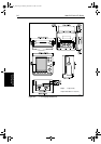
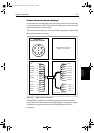
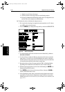
Scanner Connection (master displays)
Connect the inter-unit cable plug to the rear scanner connector. If you are using
an inter-unit extension cable, connect this to the display unit, and connect the
supplied cable to the extension cable.
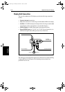
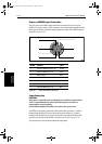
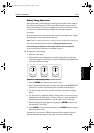
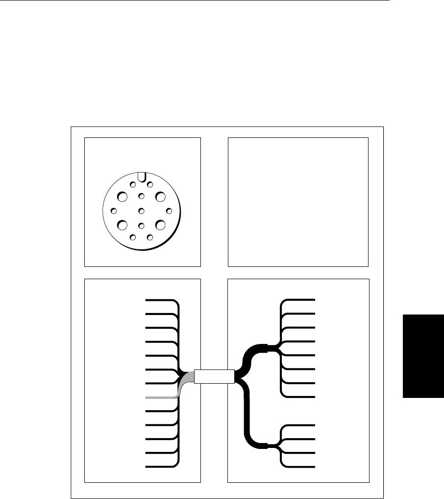
The scanner connector pins are shown in the following diagram, together with
the connections and core colours.
Figure 8-6: Radar Scanner Connection
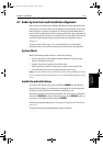
The
hsb
2
cable is supplied with a blanking plug for the scanner connector
socket. This should be attached to the repeater display. If the repeater display
is installed in an exposed position seal the blanking plate with silicon
compound.
1
2
35
4
7
10
11
86
9
13 12
White
Black
Orange
Black
Black
Green
Yellow
Shield
Red
Red
Violet
Blue
Grey
Video
Video RTN
*Battery --ve
Tx Trigger +
Battery --ve
Data I/O +
Tx Trigger --
Battery +ve
Data I/O --
*Battery +ve
Azimuth +
Azimuth --
1
2
3
4
5
6
7
8
9
10
11
12
13
White
Black
Orange
Yellow
Green
Blue
Violet
Grey
Red
Red
Black
Black
8
7
6
5
4
3
2
1
Video
Video Rtn
Tx Trigger +
Tx Trigger --
Data I/O +
Data I/O --
Azimuth +
Azimuth --
Battery +ve
*Battery +ve
*Battery --ve
Battery --ve
D4290B-2
Front view of
Display Cable Connector
Refer to Pathfinder Scanner Owner's
Handbook for connector detail.
Display Scanner
* Not present on 'light', 11 core cables.
Battery +ve/--ve = 12, 24 or 32v.
81186_2.book Page 13 Monday, December 17, 2001 8:35 AM