


VLF SUBSECTION PAGES
NOTE: The sensor SUBSECTION Pages may be accessed by plac-
ing the cursor over the individual position sensor and pressing the
ENT Key. Use the NAV, PRV or NXT Key to page through the sen-
sor SUBSECTION pages.
Accessed through the NAVIGATION 4/4 Page (if AFIS is installed in
the system, access is through the NAVIGATION 4/5 Page) by press-
ing the Line Select Key corresponding to the VLF sensor, then press-
ing ENT.
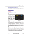
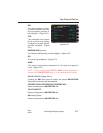
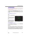
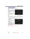
VLF SUBSECTION 1/4 (Page 1 of 4)
POS:
Same as on NAVIGATION 4/4.
VLF:
The actual position computed
by the sensor, when in the
NAV mode. (Figure 2-25)
DIF:
The difference between the
composite position and the
sensor computed position in
degrees, minutes and hun-
dredths. (Figure 2-25)
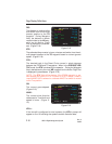
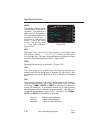
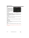
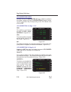
VLF SUBSECTION 2/4 (Page 2 of 4)
Pressing the NXT Key will display the second VLF SUBSECTION
Page and the following can be observed.
QUALITY:
Quality Factor is a numerical display that indicates the reliability of
position data and determines the weight of the VLF/Omega Sensor
input to the composite position. The number will range from 2 to 7
(with 2 being optimum) in the primary navigation mode, and from 8 to
99 in the dead reckoning mode (DR). NO STD will be displayed if the
rubidium frequency standard in the RPU is unstable. (Figure 2-26)
Page Display Definitions
2-21
GNS-XL Flight Management System
Rev. 0
Oct/96
POS N 38 49.90
W094 53.40
VLF N 38 49.90
W094 53.40
DIF‘ N 0.00
E 0.00
VLF SUBSECTION 1/4
Figure 2-25