


190-00592-06 Rev. A
Garmin G1000 Pilot’s Guide for the Diamond DA40/40F
77
ENGINE INDICATION SYSTEM
SYSTEM
OVERVIEW
FLIGHT
INSTRUMENTS
EIS
AUDIO PANEL
& CNS
FLIGHT
MANAGEMENT
HAZARD
AVOIDANCE
AFCS
ADDITIONAL
FEATURES
APPENDICES INDEX
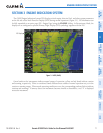
SECTION 3 ENGINE INDICATION SYSTEM
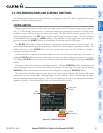
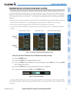
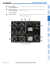
The G1000 Engine Indication System (EIS) displays critical engine, electrical, fuel, and other system parameters
on the left side of the Multi Function Display (MFD) during normal operations (Figure 3-1). EIS information can
be fully expanded to an entire page (EIS - Engine Page) using the ENGINE Softkey. In Reversionary Mode, the
displays are re-configured to present Primary Flight Display (PFD) symbology together with the EIS.
EIS Display
Figure 3-1 MFD (DA40)
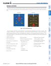
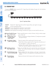
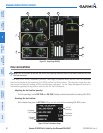
Green bands on the instruments indicate normal ranges of operation; yellow and red bands indicate caution
and warning, respectively. White or uncolored bands indicate areas outside of normal operation not yet in the
caution or warning ranges. When unsafe operating conditions occur, the corresponding readouts flash to indicate
cautions and warnings. If sensory data to an instrument becomes invalid or unavailable, a red “X” is displayed
across the instrument.