


190-00592-06 Rev A
Garmin G1000 Pilot’s Guide for the Diamond DA40/40F
407
ADDITIONAL FEATURES
SYSTEM
OVERVIEW
FLIGHT
INSTRUMENTS
EIS
AUDIO PANEL
& CNS
FLIGHT
MANAGEMENT
HAZARD
AVOIDANCE
AFCS
ADDITIONAL
FEATURES
APPENDICES INDEX
SVS FEATURES
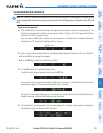
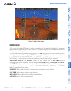
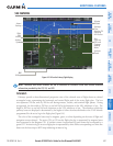
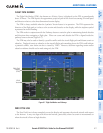
Figure 8-3 SVS on the Primary Flight Display
SVS
Softkeys
Synthetic
Terrain
Pathways
Color
Matches CDI
Indicating
NAV Source
Flight
Path
Marker
Airport
Runway
Zero
Pitch Line
(ZPL) with
Compass
Heading
Marks
Airplane
Symbol
Selected
Altitude
NOTE: Pathways and terrain features are not a substitute for standard course and altitude deviation
information provided by the CDI, VSI, and VDI.
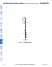
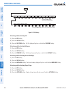
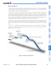
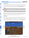
PATHWAYS
Pathways provide a three-dimensional perspective view of the selected route of flight shown as colored
rectangular boxes representing the horizontal and vertical flight path of the active flight plan. The box
size represents 700 feet wide by 200 feet tall during enroute, oceanic, and terminal flight phases. During
an approach, the box width is 700 feet or one half full scale deviation on the HSI, whichever is less. The
height is 200 feet or one half full scale deviation on the VDI, whichever is less. The altitude at which the
pathway boxes are displayed is determined by the higher of either the selected altitude or the VNAV altitude
programmed for the active leg in the flight plan (Figure 8-4).
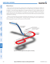
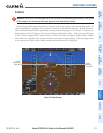
The color of the rectangular boxes may be magenta, green, or white depending on the route of flight and
navigation source selected. The active GPS or GPS overlay flight plan leg is represented by magenta boxes
that correspond to the Magenta CDI. A localizer course is represented by green boxes that correspond to a
green CDI. An inactive leg of an active flight plan is represented by white boxes corresponding to a white line
drawn on the Inset map or MFD map indicating an inactive leg.