


190-00592-06 Rev A
Garmin G1000 Pilot’s Guide for the Diamond DA40/40F
411
ADDITIONAL FEATURES
SYSTEM
OVERVIEW
FLIGHT
INSTRUMENTS
EIS
AUDIO PANEL
& CNS
FLIGHT
MANAGEMENT
HAZARD
AVOIDANCE
AFCS
ADDITIONAL
FEATURES
APPENDICES INDEX
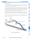
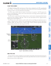
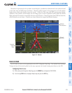
FLIGHT PATH MARKER
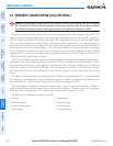
The Flight Path Marker (FPM), also known as a Velocity Vector, is displayed on the PFD at groundspeeds
above 30 knots. The FPM depicts the approximate projected path of the aircraft accounting for wind speed
and direction relative to the three-dimensional terrain display.
The FPM is always available when the Synthetic Terrain feature is in operation. The FPM represents the
direction of the flight path as it relates to the terrain and obstacles on the display, while the airplane symbol
represents the aircraft heading.
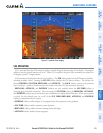
The FPM works in conjunction with the Pathways feature to assist the pilot in maintaining desired altitudes
and direction when navigating a flight plan. When on course and altitude the FPM is aligned inside the
pathway boxes as shown (Figure 8-7).
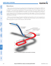
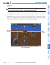
The FPM may also be used to identify a possible conflict with the aircraft flight path and distant terrain or
obstacles. Displayed terrain or obstacles in the aircraft’s flight path extending above the FPM could indicate
a potential conflict, even before an alert is issued by TAWS. However, decisions regarding terrain and/or
obstacle avoidance should not be made using only the FPM.
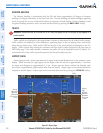
Flight Path
Marker
(FPM)
Wind
Vector
Figure 8-7 Flight Path Marker and Pathways
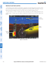
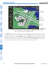
ZERO PITCH LINE
The Zero Pitch Line is drawn completely across the display and represents the aircraft attitude with respect
to the horizon. It may not align with the terrain horizon, particularly when the terrain is mountainous or
when the aircraft is flown at high altitudes.