


190-00592-06 Rev. A
Garmin G1000 Pilot’s Guide for the Diamond DA40/40F
9
SYSTEM OVERVIEW
SYSTEM
OVERVIEW
FLIGHT
INSTRUMENTS
EIS
AUDIO PANEL
& CNS
FLIGHT
MANAGEMENT
HAZARD
AVOIDANCE
AFCS
ADDITIONAL
FEATURES
APPENDICES INDEX
1.4 SYSTEM OPERATION
NOTE: Refer to Appendix A for detailed descriptions of all alerts and annunciations. Refer to the Aircraft
Flight Manual (AFM) for additional information regarding pilot responses to these annunciations.
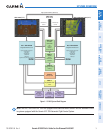
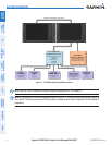
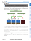
The displays are connected together via a single Ethernet bus for high-speed communication. As shown in
Figure 1-1, each IAU is connected to the on-side display. This allows the units to share information, enabling true
system integration
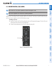
DISPLAY OPERATION
NOTE:
In normal operating mode, backlighting can only be adjusted from the PFD. In Reversionary Mode, it
can be adjusted from the remaining display.
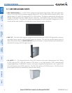
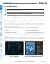
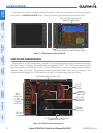
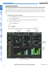
In normal operating mode, the PFD presents graphical flight instrumentation (attitude, heading, airspeed,
altitude, vertical speed), replacing the traditional flight instrument cluster (see the Flight Instruments Section
for more information). The MFD normally displays a full-color moving map with navigation information (see
the Flight Management Section), while the left portion of the MFD is dedicated to the Engine Indication System
(EIS; see the EIS Section). Both displays offer control for COM and NAV frequency selection.
Figure 1-6 G1000 Normal Operation
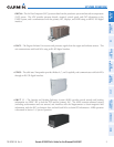
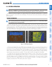
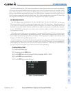
In the event of a display failure, the G1000 System automatically switches to reversionary (backup) mode. In
Reversionary Mode, all important flight information from the PFD is presented on the remaining display in the
same format as in normal operating mode, with the addition of the EIS. EIS operation while in Reversionary
Mode is discussed in the EIS Section. As when the PFD is operating normally, windows for flight planning,
nearest airports, and procedures are available. The Inset Map is moved to the right side of the display.
If a display fails, the appropriate IAU-display Ethernet interface is cut off. Thus, the IAU can no longer
communicate with the remaining display (refer to Figure 1-1), and the NAV and COM functions provided to
the failed display by the IAU are flagged as invalid on the remaining display. The system reverts to backup
paths for the AHRS, ADC, Engine/Airframe Unit, and Transponder, as required. The change to backup paths is
completely automated for all LRUs and no pilot action is required.