


CI-ControlWave EFM Installation & Operation / 2-47
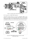
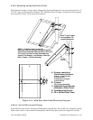
2.3.9.3 Mounting an Optional Solar Panel
Solar Panels (used to charge the rechargeable lead acid batteries) are to be mounted to a 2”
to 2-3/8” pipe as illustrated in Figure 2-35. Muffler (Pipe) Clamps, utilized for this purpose,
are secured via four 1/4-20 nuts and washers.
2-3/8 U-Clamp Assembly
B - 2 places:
NOTE 1: To Attach item C to item D:
Slide two bolts (A) through the top and bottom
Solar Panel (Centered) Channel Holes. Affix item
C to item D via 2 sets of item A hardware as
follows: Flat Washer, Lock Washer & Hex Nut
(Max. Torque = 120 Inch-Pounds).
Note 2: Item D slot
s
accommodate Tilt
Angle Adjustment.
Adjustable
Tilt Angle
Vertical
Pole
C - Adjustable Angle Bracket
(Attaches to Solar Panel)
D - Pole Mounting Bracket
E - 30 or 40 Watt Solar Panel
5/16-18 x .75 Hex Hd. Bolt
5/16 Flat Washer
5/16 Spring Lock Washer
5/16-18 Hex Nut
A - 6 places consists of
the following hardware:
B
B
A
A
A
C
D
E
A
B
B
A
A
A
D
C
E
A
B
A
A
A
C
D
E
Figure 2-35 - 30/40 Watt Solar Panel Mounting Diagram
2.3.9.3.1 Swivel (Directional Facing)
Solar Panels used in the Northern Hemisphere should face due south (not magnetic south)
while those used in the southern hemisphere should face due north (not magnetic north).